
Page 428 - House of Maxell
P. 428
408 Chapter 8
8.3.5 Power Combiner/Splitter Networks
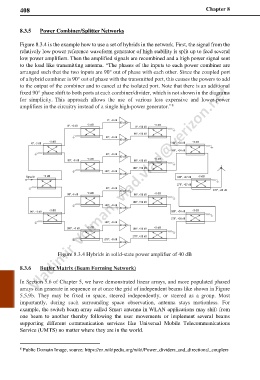
Figure 8.3.4 is the example how to use a set of hybrids in the network. First, the signal from the
relatively low power reference waveform generator of high stability is split up to feed several
low power amplifiers. Then the amplified signals are recombined and a high power signal sent
to the load like transmitting antenna. “The phases of the inputs to each power combiner are
arranged such that the two inputs are 90° out of phase with each other. Since the coupled port
of a hybrid combiner is 90° out of phase with the transmitted port, this causes the powers to add
to the output of the combiner and to cancel at the isolated port. Note that there is an additional
fixed 90° phase shift to both ports at each combiner/divider, which is not shown in the diagrams
for simplicity. This approach allows the use of various less expensive and lower-power
8
amplifiers in the circuitry instead of a single high-power generator.”
Figure 8.3.4 Hybrids in solid-state power amplifier of 40 dB
8.3.6 Butler Matrix (Beam Forming Network)
In Section 5.6 of Chapter 5, we have demonstrated linear arrays, and more populated phased
arrays can generate in sequence or at once the grid of independent beams like shown in Figure
5.5.9b. They may be fixed in space, steered independently, or steered as a group. Most
importantly, during such surrounding space observation, antenna stays motionless. For
example, the switch beam array called Smart antenna in WLAN applications may shift from
one beam to another thereby following the user movements or implement several beams
supporting different communication services like Universal Mobile Telecommunications
Service (UMTS) no matter where they are in the world.
8 Public Domain Image, source: https://en.wikipedia.org/wiki/Power_dividers_and_directional_couplers