
Page 178 - Mold Bases & Plates 2020
P. 178
X-, AX- and T-Series Mold Bases
186
7c
7 /8" T-Series (3-Plate) Mold Bases
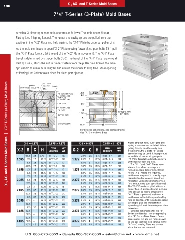
A typical 3-plate top runner mold operates as follows: The mold opens first at
Parting Line 1 (spring loaded). The runner and cavity sprues are pulled from the
cavities in the “X-2” Plate and held against the ”X-1” Plate by undercut puller pins.
As the mold continues to open (“X-2” Plate moving forward), stripper bolts SB-1 pull
the “X-1” Plate forward (at the end of the “X-2” Plate movement). The “X-1” Plate
travel is determined by stripper bolts SB-2. The travel of the “X-1” Plate (breaking at
Parting Line 2) strips the entire runner system from the puller pins, breaks the main
sprue (held to a minimum length), and allows the runner to drop free. Mold opening
at Parting Line 3 then takes place for piece-part ejection.
X-, AX- and T-Series Mold Bases | 7 7 /8" T-Series (3-Plate) Mold Bases
CAVITY SPRUE
RUNNER PIECE PART SPRING
MAIN SPRUE PULLER PIN SB-2
1.875 A.C.P.
“A”- CLAMPING PLATE
PARTING LINE 2 X-1
“X-1” PLATE
PARTING LINE 1 L
SB-1 “X-2” PLATE X-2
PARTING LINE 3
H
“B” PLATE B (MOLD SHUT
1.375 HEIGHT)
SUPPORT PLATE
C
EJECTOR HOUSING 0.875 W
For detailed dimensions, see corresponding
size “A“ Series Mold Base
X-1 = 0.875 7.875 × 7.875 X-1 = 0.875 7.875 × 11.875 note: Stripper bolts, puller pins and
spring shown are not included. When
x-2 b c H nUMber net x-2 b c H nUMber net gating directly into the cavity from
iteM
iteM
a top runner, the 3-plate “T” Series
wt.
wt.
assembly may be used. It incorporates
0.875 2.5 9.75 88T-13-7 153 0.875 2.5 9.75 812T-13-7 237 an additional runner stripper plate
1.375 1.375 2.5 10.25 88T-13-13 162 1.375 1.375 3 10.75 812T-13-13 254 (“X-1”) to facilitate automatic removal
1.875 2.5 10.75 88T-13-17 171 1.875 3 11.25 812T-13-17 268 of the runner from the mold.
The “X-1” and “X-2” Plates have
0.875 2.5 10.25 88T-17-7 162 0.875 2.5 10.25 812T-17-7 250 standard shoulder bushings and
1.875 1.375 2.5 10.75 88T-17-13 171 1.875 1.375 3 11.25 812T-17-13 268 ride on standard leader pins. (When
1.875 2.5 11.25 88T-17-17 180 1.875 3.5 12.25 812T-17-17 285 heavy “X-2” Plates are required,
1.375 2.5 11.25 88T-23-13 180 1.375 3 11.75 812T-23-13 281 moldmaker may want to specify larger
diameter leader pins and have them
2.375 1.875 2.5 11.75 88T-23-17 188 2.375 1.875 3.5 12.75 812T-23-17 298 relocated. Contact customer service
2.375 3 12.75 88T-23-23 200 2.375 3.5 13.25 812T-23-23 312 for a quotation to your specifications).
1.375 3 12.25 88T-27-13 191 1.375 3 12.25 812T-27-13 294 The “X-1” Plate is supplied without a
2.875 1.875 3.5 13.25 88T-27-17 203 2.875 1.875 3.5 13.25 812T-27-17 312 center hole. A standard sprue bushing
long enough to extend through the
2.375 3.5 13.75 88T-27-23 212 2.375 3.5 13.75 812T-27-23 325 “X-1” Plate is provided to allow the
1.875 3.5 13.75 88T-33-17 212 1.875 3.5 13.75 812T-33-17 325 moldmaker to finish the sprue bushing
3.375 2.375 4 14.75 88T-33-23 223 3.375 2.375 4 14.75 812T-33-23 342 hole as desired, or to install a recessed
2.875 4 15.25 88T-33-27 232 2.875 4 15.25 812T-33-27 355 bushing to give the shortest main
sprue length for minimum stripper plate
1.875 3.5 14.25 88T-37-17 220 1.875 3.5 14.25 812T-37-17 338 movement.
3.875 2.375 4 15.25 88T-37-23 232 3.875 2.375 4 15.25 812T-37-23 355 Detailed dimensions for the “T”
2.875 4 15.75 88T-37-27 241 2.875 4 15.75 812T-37-27 369 Series are identical to corresponding
2.375 4 16.25 88T-47-23 250 2.375 4 16.25 812T-47-23 382 size “A” Series Mold Bases. Center
sprue puller pin and pin holes as well
4.875 2.875 4 16.75 88T-47-27 258 4.875 2.875 4 16.75 812T-47-27 395 as the socket head cap screws in the
3.375 4.5 17.75 88T-47-33 270 3.375 4.5 17.75 812T-47-33 413 “A” — Clamping Plate are omitted
since the are not required.
U.S. 800-626-6653 ■ Canada 800-387-6600 ■ sales@dme.net ■ www.dme.net