Page 178 - Corkjoint E-Catalogue
P. 178

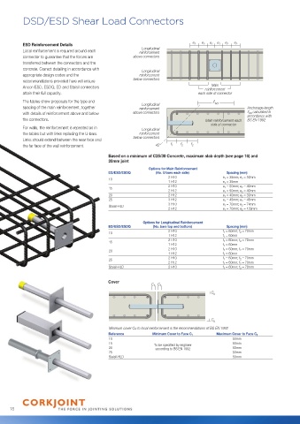
DSD/ESD Shear Load Connectors


          ESD Reinforcement Details                                           e 2  e 2  e 1  e 1  e 2  e 2
                                                         Longitudinal
          Local reinforcement is required around each   reinforcement
          connector to guarantee that the forces are   above connectors
          transferred between the connectors and the
          concrete. Correct detailing in accordance with   Longitudinal
          appropriate design codes and the              reinforcement
          recommendations provided here will ensure   below connectors
                                                                                     Main
          Ancon ESD, ESDQ, ED and Staisil connectors                              reinforcement
          attain their full capacity.                                           each side of connector
          The tables show proposals for the type and                                  bd
                                                         Longitudinal
          spacing of the main reinforcement, together   reinforcement                              Anchorage length
          with details of reinforcement above and below   above connectors                            bd  calculated in
                                                                                                   accordance with
          the connectors.                                                          Main reinforcement each   BS EN 1992
                                                                                     side of connector
          For walls, the reinforcement is repeated as in   Longitudinal
          the tables but with links replacing the U-bars.   reinforcement
          Links should extend between the near face and   below connectors
          the far face of the wall reinforcement.              45°   f 1  f 2  f 2
                                            Based on a minimum of C25/30 Concrete, maximum slab depth (see page 16) and
                                            20mm joint
                                                             Options for Main Reinforcement
                                            ED/ESD/ESDQ        (No. U bars each side)      Spacing (mm)
                                                                    2 H10                e 1  = 35mm; e 2  = 50mm
                                            10
                                                                    1 H12                e 1  = 35mm
                                                                    2 H10                e 1  = 50mm; e 2  = 40mm
                                            15
                                                                    2 H12                e 1  = 50mm; e 2  = 40mm
                                            20                      2 H12                e 1  = 40mm; e 2  = 30mm
                                            25                      3 H12                e 1  = 45mm; e 2  = 45mm
                                                                    3 H10                e 1  = 70mm; e 2  = 74mm
                                            Staisil-HLD
                                                                    2 H12                e 1  = 70mm; e 2  = 139mm
                                                          Options for Longitudinal Reinforcement
                                            ED/ESD/ESDQ       (No. bars top and bottom)    Spacing (mm)
                                                                    2 H10                f 1  = 60mm; f 2  = 70mm
                                            10
                                                                    1 H12                f 1  = 60mm
                                                                    2 H10                f 1  = 60mm; f 2  = 70mm
                                            15
                                                                    1 H12                f 1  = 60mm
                                                                    2 H10                f 1  = 60mm; f 2  = 70mm
                                            20
                                                                    1 H12                f 1  = 60mm
                                                                    2 H10                f 1  = 60mm; f 2  = 70mm
                                            25
                                                                    2 H12                f 1  = 60mm; f 2  = 70mm
                                            Staisil-HLD             2 H10                f 1  = 60mm; f 2  = 70mm
                                            Cover
                                                             C f C f
                                                                                     C u


                                                                                     C u
                                            Minimum cover Cu to local reinforcement is the recommendations of BS EN 1992
                                            Reference         Minimum Cover to Face C f    Maximum Cover to Face C f
                                            10                                               50mm

                                            15                To be specified by engineer      50mm
                                            20                 according to BS EN 1992       50mm

                                            25                                               50mm
                                            Staisil-HLD                                      50mm


     18
   173   174   175   176   177   178   179   180   181   182   183