Page 47 - Parker - Hydraulic and Lube Filtration Products
P. 47

™
               Modufl ow           Series                                               Drawings are for reference only.
                                                                                       Contact factory for current version.
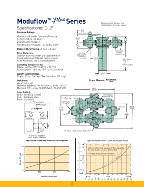
               Specifi cations: DILP
                                                                      3.3
               Pressure Ratings:                                      .013
               Maximum Allowable Operating Pressure              116.8
               (MAOP): 200 psi (13.8 bar)                         4.60                                     79.0
                                                                                                           3.11
               Design Safety Factor: 2:1
               Rated Fatigue Pressure: 150 psi (10.3 bar)         76.2
                                                                  3.00
               Element Burst Rating: 70 psid (4.8 bar)
                                                                                                   ½-13 SHCS
               Filter Materials:                                    ¼-18 NPT                       32-38 FT-LB
                                                                                                    TORQUE
               Diverter Valve Assembly: die cast aluminum         DRAIN VENT
                                                                    CONNECT
               Check Valve Assembly: die cast aluminum               TO TANK     173.0                   330.2
                                                                                 6.81                        SINGLE
               Filter Assembly: see IL2 specifi cations                                                    13.0
               Operating Temperatures:                                                                   617.5  DOUBLE
                                                                                                         24.31
               Nitrile: -40°F to 225°F (-40°C to 107°C)
               Fluorocarbon: -15°F to 275°F (-26°C to 135°C)
                                                                                       110.5
               Weight (approximate):
                                                                                       4.61
               Single:  55 lbs. (24.9 kg) / Double: 65 lbs. (29.5 kg)
               Indicators:                                                   Linear Measure:   millimeter
                                                                                              inch
               Visual (optional)
               Electrical (optional) 15A @ 250VAC/.5A @ 125 VDC
               Electrical (“D” option) 5A @ 250VAC / 3A @ 28 VDC                467.0
                                                                                18.38
               Color Coding:
               White (normally closed)                                                   AIR BLEED
                                                                                         EACH FILTER
               Red   (normally open)                    30.2
               Black (common)                           1.19
                          FILTER SCHEMATIC            OPTIONAL
                                                       FLANGE
                                   OUTLET
                                                                                                      OUTLET    402.8
                                                   345.9                                                        15.86
                                                   13.62
                         FILTER   FILTER
                                                       INLET                                               177.8
                                                                                                           7.00
                       BYPASS      BYPASS


                                   DRAIN
                        INLET      VENT                OPTIONAL MECHANICAL INDICATOR
                          BOTH CHECK VALVES
                         MOVE SAME DIRECTION
                       Approximate handle torque required for changeover.  Typical Flow/Pressure Curves For Duplex Valves
                                                                        25
                                                                  1.75
                   30                                                   BAR
                                                                            ( (A
                                                                   1.5      (Add to differential pressure of filter assembly  Add to differential pressure of filter assembly  dd to differential pressure of filter assembly
                                                                            f for total duplex pressure differential)
                                                                        20  for total duplex pressure differential) or total duplex pressure differential)

                                                                  1.25      *Diverter/check valves combined Diverter/check valves combined
                                                                            * *Diverter/check valves combined
                   Torque  (Ft-Lbs)                               0.75 1  DIFF . PRESSURE  15      3000 SUS
                   20
                                                                                                    200 SUS
                                                                        10
                   10
                                                                   0.5
                                                                         5
                    0                                             0.25  PSID
                      0          100          200          300
                                                                    0
                                                                          0  10  20  30  40  50  60  70  80  90  100
                                    System Pressure (psi)
                                                                           GPM             FLOW             LP M
                                                                          0  25  50  75 100 125 150 175 200 225 250 275 300 325  375
                                                             42
   42   43   44   45   46   47   48   49   50   51   52