
Page 54 - Parker - Hydraulic and Lube Filtration Products
P. 54
™
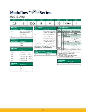
Modufl ow Series
How to Order
BOX 1 BOX 2 BOX 3 BOX 4 BOX 5 BOX 6 BOX 7 BOX 8
ILP 1 10Q B MP 35 Y9Y9 1
BOX 1: Filter BOX 5: Indicator BOX 7: Port Options
Series Symbol Description Symbol Description
Filter Inlet Outlet
RFP Return-line fi lter, inlet on P Pressure ports drilled & Model Symbol/Description Symbol/Description
side outlet on bottom plugged only; no indicator
Y9 2” fl ange face 99 No fi tting
ILP In-line fi lter M Visual indicator w/”no P9 SAE-24 F9 2” NPTF
element” warning RFP
DILP In-line duplex integral threads
E Electrical indicator only F8 External check
BOX 2: Element D Electrical indicator only, valve
Length Symbol Description 3-pin male receptacle Y9 2” fl ange face Y9 2” fl ange face
1 Single ILP P9 SAE-24 P9 SAE-24 integral
Note: First letter of indicator code = left side integral threads threads
2 Double of fi lter head when looking into inlet with bowl
down; second letter = right side of fi lter head E9 1½ NPTF
when looking into inlet with bowl down. integral threads
BOX 3: Media DILP Y9 2” fl ange face Y9 2” fl ange face
Code Symbol Description 1) First pair of symbols denotes inlet for all fi lter
BOX 6: Bypass Setting styles; second pair of symbols denotes outlet.
02Q Microglass III, 2 micron Symbol Description 2) Four symbols required: two for inlet, two for outlet.
3) Unused ports in fi lters come plugged
05Q Microglass III, 5 micron 35 35 psid with a blank fl ange.
4) See Flange Kits table for port fl ange options.
10Q Microglass III, 10 micron Flange Kits are ordered separately.
20Q Microglass III, 20 micron
WR Water Removal BOX 8: Options
Symbol Description
BOX 4: Seals
1 None
Symbol Description
B Nitrile
E EPR
V Fluorocarbon
49