
Page 268 - Schroeder - Hydraulic And Lube Filtration
P. 268
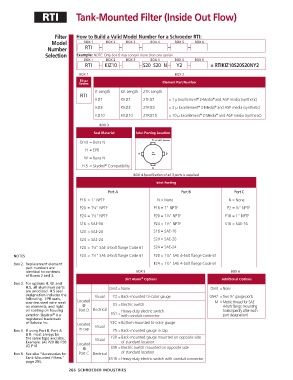
RTI           Tank-Mounted Filter (Inside Out Flow)


                        Filter   How to Build a Valid Model Number for a Schroeder RTI:
                       Model        BOX 1    BOX 2    BOX 3     BOX 4     BOX 5   BOX 6
                     Number          RTI   –       –       –           –        –
                    Selection    Example: NOTE: Only box 6 may contain more than one option
                                    BOX 1    BOX 2    BOX 3     BOX 4     BOX 5   BOX 6
                                     RTI   – KIZ10 –       – S20  S20  N –  Y2  –        = RTIKIZ10S20S20NY2

                                  BOX 1                                   BOX 2
                                  Filter
                                  Series                             Element Part Number
                                         K Length   KK Length  27K Length
                                   RTI
                                         KIZ1       KKIZ1    27KIZ1     = 1 µ Excellement  Z-Media and ASP media (synthetic)
                                                                                   ®
                                                                                          ®
                                                                                           ®
                                                                                    ®
                                         KIZ3       KKIZ3    27KIZ3     = 3 µ Excellement  Z-Media  and ASP media (synthetic)
                                                                                     ®
                                         KIZ10      KKIZ10   27KIZ10    = 10 µ Excellement  Z-Media  and ASP media (synthetic)
                                                                                           ®
                                           BOX 3
                                        Seal Material     Inlet Porting Location
                                  Omit = Buna N
                                     H = EPR
                                    W = Buna N

                                   H.5 =  Skydrol  Compatibility
                                             ®
                                                         BOX 4 Specification of all 3 ports is required
                                                                  Inlet Porting
                                              Port A                         Port B                Port C

                                  P16 = 1" NPTF                    N = None                      N = None
                                  P20 = 1 ⁄4" NPTF               P16 = 1" NPTF                  P2 =  ⁄8" NPTF
                                        1
                                                                                                    1
                                  P24 = 1 ⁄2" NPTF               P20 = 1 ⁄4" NPTF              P16 = 1" NPTF
                                                                       1
                                        1
                                  S16 = SAE-16                   P24 = 1 ⁄2" NPTF              S16 = SAE-16
                                                                       1
                                  S20 = SAE-20                   S16 = SAE-16
                                  S24 = SAE-24                   S20 = SAE-20
                                  F20 =  1 ⁄4" SAE 4-bolt flange Code 61  S24 = SAE-24
                                        1
                                                                       1
                                        1
       NOTES:                     F24 =  1 ⁄2" SAE 4-bolt flange Code 61  F20 =  1 ⁄4" SAE 4-bolt flange Code 61
                                                                       1
       Box 2.   Replacement element                              F24 =  1 ⁄2" SAE 4-bolt flange Code 61
            part numbers are
            identical to contents                         BOX 5                                  BOX 6
            of Boxes 2 and 3.
                                                            ®
                                                     Dirt Alarm  Options                      Additional Options
       Box 3.   For options H, W, and
            H.5, all aluminum parts            Omit = None                               Omit =  None
            are anodized. H.5 seal
            designation includes the     Visual  Y2 = Back-mounted tri-color gauge       G547 =  Two  ⁄8" gauge ports
                                                                                                 1
            following:  EPR seals,   Located
            stainless steel wire mesh           ES =  Electric switch                      M =  Metric thread for SAE
            on elements, and light   @                                                        4-bolt flange mounting
            oil coating on housing   Port D Electrical    Heavy-duty electric switch          holes (specify after each
                       ®
            exterior. Skydrol  is a            ES1 = with conduit connector                   port designation)
            registered trade mark
            of Solutia Inc.      Located       Y2C = Bottom-mounted tri-color gauge
       Box 4.    If using Port B, Port A   in cap  Visual  Y5 = Back-mounted gauge in cap
            & B  must always be
            the same type and size.      Visual  Y2R =  Back-mounted gauge mounted on opposite side
            Example: (A) P20 (B) P20    Located     of standard location
            (C) P16                            ESR =  Electric switch mounted on opposite side
                                    @
       Box 6.   See also “Accessories for    Port C Electrical  of standard location
            Tank-Mounted Filters,”             ES1R =  Heavy-duty electric switch with conduit connector
            page 295.
                              266  SCHROEDER INDUSTRIES