Page 154 - Wago_AutomationTechnology_Volume3_2015_US.pdf
P. 154

750-306

   4    DeviceNet Fieldbus Coupler

  152   125 ... 500 Kbaud; digital and analog signals


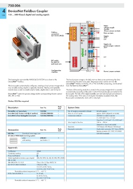
                                                                          DeviceNet   01  02   Status
                                                                           OVERFL   A         voltage supply
                                                                           MS       C         -System
                                                                           RUN   B   D        -Power jumper contacts
                                               Fieldbus                    BUS OFF            Data contacts
                                               connection                  NS   24V  0V
                                               231 Series (MCS)            CONNECT            Supply
                                                                                              24 V
                                                                                              0 V
                                                                           I/O
                                                                                 +  +
                                                                                              Supply via
                                                                                              power jumper contacts
                                                                                              24 V
                                                                            W  750-306  —  —


                                               DIP switch            ON                       0 V
                                               for MAC ID         1 2 3 4 5 6 7 8
                                               and baud rate


                                               Configuration                                   Power jumper contacts
                                               interface


        This buscoupler connects the WAGO-I/O-SYSTEM as a slave to the   The local process image is divided into two data zones containing the data
               TM
        DeviceNet  fieldbus.                                received and the data to be sent. The process data can be sent via the
                                                                   TM
                                                            DeviceNet  fieldbus to the PLC, PC or NC for further processing, and received
                                                                               TM
        The buscoupler automatically configures, creating a local process image which  from the field via DeviceNet .
        may include analog, digital or specialty modules. Analog and specialty
        module data is sent via words and/or bytes, digital data is sent bit by bit.  The data of the analog modules is stored in the process image which is created
                                                            automatically according to the order in which the modules are connected to the
               TM
        DeviceNet  stores the process image in the corresponding Master control   buscoupler. The bits of the digital modules are sent byte by byte and added to
        (PLC, PC or NC).                                    the analog data. If the amount of digital information exceeds 8 bits, the
                                                            buscoupler automatically starts with a new byte.
        Notice: EDS files required
        Description                  Item No.        Pack.    System Data
                                                     Unit
        DeviceNet, w/ status byte    750-306         1        No. of couplers connected to Master  64 with scanner
        DeviceNet (only function with digital modules)  750-306/000-005  1  Max. no. of I/O points  approx. 6000 (depends on master)
        DeviceNet (without buskoppler status byte)  750-306/000-006  1  Transmission medium  Shielded Cu cable Trunk line:
                                                                                       2 x 0.82 mm² + 2 x 1.7 mm²
                                                                                       Drop line: 2 x 0.2 mm² + 2 x 0.32 mm²
                                                              Max. length of bus line  100 m ... 500 m
                                                                                       (depends on baud rate/cable)
                                                              Baud rate                125 Kbaud, 250 Kbaud, 500 Kbaud
        Accessories                  Item No.        Pack.    Buscoupler connection    5-pole male connector, 231 Series (MCS),
                                                     Unit                              female connector 231-305/ 010-000/
        EDS files    Download: www.wago.com                                            050-000 (included)
        Miniature WSB Quick marking system
                     plain           248-501         5
                     with marking    see Section 11


        Approvals
        Certification             ODVA
        Conformity marking        1
        Korea Certification
        Marine applications (versions upon request)  ABS, BV, DNV, GL, KR, LR, NKK, PRS, RINA
        r UL 508
        r ANSI/ISA 12.12.01       Class I, Div. 2, Grp. ABCD, T4
        4 TÜV 07 ATEX 554086 X    I M2 Ex d I Mb,
                                  II 3 G Ex nA IIC T4 Gc,
                                  II 3 D Ex tc IIIC T135°C Dc
              Permissible ambient temperature 0 °C ... +60 °C
        IECEx TUN 09.0001 X       Ex d I Mb,
                                  Ex nA IIC T4 Gc,
                                  Ex tc IIIC T135°C Dc
              Permissible ambient temperature 0 °C ... +60 °C
   149   150   151   152   153   154   155   156   157   158   159