Page 257 - Wago_AutomationTechnology_Volume3_2015_US.pdf
P. 257

750-472, 750-474 / 753-472, 753-474

           2-Channel Analog Input Module 0/4-20 mA                                                                 4

           Single-ended (S.E.)                                                                                      255


                            13 14
                           A
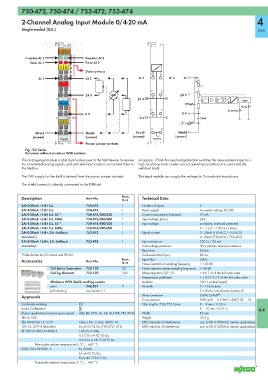
            Function AI 1      C       Function AI 2
                           B
              Error AI 1       D       Error AI 2
                            E1  E2
                                       Data contacts
                                                                    1    5
                  AI 1                 AI 2                    AI 1         AI 2   AI
                            +  +
                                                                                           I
                                                                    2    6

                                       24 V                                      24 V
                                                              24 V                                   A      Logic
                           0V  0V                                                  270pF              D
                                                                                                            Error
                                                                    3    7                            Function

                                       0 V                                        0 V
                                                               0 V                        10nF
                            S  S
                                                                    4    8
                 Shield                Shield                Shield             Shield
                (screen)               (screen)             (screen)           (screen)
                            750-472                                  750-472
                                       Power jumper contacts
            Fig. 750 Series
            Delivered without miniature WSB markers
           The analog input module is able to provide power to the field device, to receive  At approx. 25mA the overload protection switches the measurement input to a
           the transmitted analog signals, and with electrical isolation, to transmit them to  high resistance state. Under normal operating conditions it is automatically
           the fieldbus.                                       switched back.
           The 24V supply for the field is derived from the power jumper contacts.  This input module can supply the voltage for 2-conductor transducers.

           The shield (screen) is directly connected to the DIN rail.

           Description                 Item No.        Pack.    Technical Data
                                                       Unit
           2AI 0-20mA 16 Bit S.E.      750-472         1        Number of inputs          2
           2AI 4-20mA 16 Bit S.E.      750-474         1        Power supply              via system voltage DC/DC
           2AI 0-20mA 16 Bit S.E. S5  1)  750-472/000-200  1    Current consumption (internal)  75 mA
           2AI 0-20mA 16 Bit S.E. 60Hz  750-472/005-000  1      Input voltage (max.)      24V
           2AI 4-20mA 16 Bit S.E. S5  1)  750-474/000-200  1    Input voltage             non-linear, overload protected
           2AI 4-20mA 16 Bit S.E. 60Hz  750-474/005-000  1                                V = 1.2 V + 100 Ω x I meas.
           2AI 0-20mA 16 Bit, S.E. (without   753-472  1        Signal current            0 - 20mA (750-472 / 753-472)
           connector)                                                                     4 - 20mA (750-474 / 753-474)
           2AI 4-20mA 16 Bit, S.E. (without   753-474  1        Input resistance          220 Ω / 20 mA
           connector)                                           Overvoltage protection    30 V polarity reversal protection
                                                                Resolution                15 bits
           1)
            Data format for S5 control with FB 251              Conversion time (typ.)    80 ms
           Accessories                 Item No.        Pack.    Input filter              50Hz
                                                       Unit     Noise rejection at sampling frequency  < -100 dB
                       753 Series Connectors  753-110  25       Noise rejection above sampling frequency  < -40 dB
                       Coding elements  753-150        100      Measuring error (25 °C)   < ± 0.1 % of the full scale value
                                                                Temperature coefficient   < ± 0.01 % / K of the full scale value
                       Miniature WSB Quick marking system       Isolation                 500 V system/supply
                       plain           248-501         5        Bit width                 2 x 16 bits data
                       with marking    see Section 11                                     2 x 8 bits control/status (optional)
           Approvals                                            Wire connection           CAGE CLAMP ®
                                                                Cross sections            0.08 mm² ... 2.5 mm² / AWG 28 ... 14
           Conformity marking       1                           Strip lengths, 750/753 Series  8 ... 9 mm / 0.33 in
           Korea Certification                                                            9 ... 10 mm / 0.37 in     4.4
           Marine applications (versions upon request)  ABS, BV, DNV, GL, KR, LR, NKK, PRS, RINA  Width  12 mm
           r UL 508                                             Weight                    55.5 g
           r ANSI/ISA 12.12.01      Class I, Div. 2, Grp. ABCD, T4  EMC immunity of interference  acc. to EN 61000-6-2, marine applications
           TÜV 12.1297 X (Brasilien)  Ex nA IIC T4 Gc (750-472, -474)  EMC emission of interference  acc. to EN 61000-6-4, marine applications
           4 TÜV 07 ATEX 554086 X   I M2 Ex d I Mb,
                                    II 3 G Ex nA IIC T4 Gc,
                                    II 3 D Ex tc IIIC T135°C Dc
                 Permissible ambient temperature 0 °C ... +60 °C
           IECEx TUN 09.0001 X      Ex d I Mb,
                                    Ex nA IIC T4 Gc,
                                    Ex tc IIIC T135°C Dc
                 Permissible ambient temperature 0 °C ... +60 °C
   252   253   254   255   256   257   258   259   260   261   262