
Page 52 - Wago_AutomationTechnology_Volume3_2015_US.pdf
P. 52
3 PFC200
50 Installation Instructions
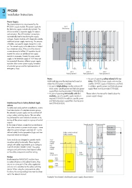
Power Supply
The internal electronics are powered by the
PFC200’s supply module. The power supply to 24 V
the field-side supply is electrically isolated. The Electronics
division enables a separate supply for sensors
and actuators. The I/O modules’ connections
automatically lead to transferring the supply
voltages. Supply modules with diagnostics enable PFC200 Supply Module Bus Module Supply Module
additional power supply monitoring. This ensures with
a flexible, user-specific supply design for a stati-
on. The current supply to the electronics is limited
by a maximum value. If the sum of the internal
current demand of all the I/O modules should
exceed this value, an additional bus supply
module is necessary. Even in this case, power
supply to the field-side supply of 10 A may not
be exceeded. However, different power supply
modules allow a new power supply, formation
of potential groups and the implementation of
emergency stops.
24 V 230 V 24 V
Field potential 1 Field potential 2 Field potential 3
Notes • As part of operating safety-related I/O mo-
Additional steps must be implemented based on dules, PELV/SELV power supply units must be
where the I/O-System is installed: used for 24 VDC supply of electronics and field.
• As part of shipbuilding or in the onshore/off- In addition, specific power and field-side power
shore sector, specific power and field-side power supply filters must be provided (750-626).
supply filters must be provided (750-624/626).
• As part of operating intrinsically safe Ex i Please refer to the manual for details about the
modules, use of a specific supply module is power supply’s design.
required (750-625). In addition, specific power
and field-side power supply filters must be provi-
Interference-Free in Safety-Related Appli- ded (750-624/626).
cations
To safely and easily perform cost-effective, centra-
lized deactivation of complete actuator groups,
the actuator’s power supply can be switched off
using a safety switching device. This can either
be performed for each individual actuator or by
turning off the power supply to a group of control
outputs.
In the event of failure, ensure that no interference Supply module Output module
from other current or power circuits occurs — even Actuator 1
when the control voltage is switched off — so the
defined safety function properties (logic and time Safety switch module/ Actuator 2
response) remain unchanged. Safety module 1 5
D01 D02
Some modules are designed to provide interfe- 24 V
rence-free safety functionality. These modules voltage Safe
supply output 1 4 2 6
comply with safety requirements up to Category
0 V
4 of DIN EN ISO 13849-1:2007. The safety voltage
category and performance level depend solely supply 24 V 24 V
on the safety components and their wiring. Safe
Safety 2 5 3 7
components output
Notice:
Safe
Interference-free WAGO I/O modules have input 0 V 0 V
no active influence on the safety function, they Logic
are not an active part of the safety application Safe
input 3 6 4 8
and are not a substitute for the safety switching
device! When using the components in safety
functions, the corresponding notes must be obser-
ved in the relevant manual.
Example: Two-channel, double-pole power supply disconnection