Page 6 - Parker - P33T series redundant safety exhaust valve
P. 6

Accessories & Technical                                                                (Revised 12-04-14)

            Information


            Technical information                               Accessories

            Pilot Solenoids:                  According to VDE 0580   Description                    Part number
            Enclosure rating:              According to DIN 400 50 IP 65   Black grill               1834C05-001
            Connector socket:            According to DIN 43650 Form A
                                  Three solenoids, rated for continuous duty  Body connector         P32KA00CB
            Standard voltages:                          24VDC   Cables
            Power consumption (each solenoid):                   M12, 5-pin female to flying lead cable,   RKC 4.5T-2/S1587
                                                                 TPE; 2 m (6.6 ft)
            For primary and reset solenoids:       1.2 watts on DC  M12, 5-pin male to flying lead cable,
            Enclosure rating:                      IP65, IEC 60529  TPE; 2 m (6.6 ft)            RSC 4.5T-2/S1587
            Electrical connection:                    M12, 5-pin  Port block kit
            Ambient temperature:          15°F to 122°F (-10°C to 50°C)    1/2 NPT                   P32KA94CP
            Media temperature:             40°F to 175°F (4°C to 80°C)  3/4 NPT                      P32KA96CP
            Flow media:       Compressed Air, filtered to minimum 40 micron  1/2 BSPP                P32KA14CP
            Inlet pressure:                 30 to 150 PSIG (2 to 10 bar)  3/4 BSPP                   P32KA16CP
                                                                 1/2 BSPT
                                                                                                     P32KA24CP
            Pressure switch (status indicator) rating:   5 amps at 30 volts DC.  3/4 BSPT            P32KA26CP
            Monitoring:   Dynamically, cyclically, internally during each actuating   Pressure switch   1227A30-001
                           and de-actuating movement. Monitoring function has
                      memory and requires an overt act to reset unit after lockout.  Pressure transducer (optional)   1232H30-001
            Mounting orientation:     Vertically with pilot solenoids on top  T-bracket w/ body connector   P32KA00MT
            Port threads:                        3/4 NPT, 3/4 BSPP  T-bracket (fits to body connector or port block)   P32KA00MB
            Control reliable:   Category 4 (Cat 4); performance Level e (PLe)   Silencer(s) 3/4"      5500A5013
                          in accordance with Machine Directive  - EN ISO 13849-1   Solenoid (main & reset)   1527B7916-001
                                               (certification pending)  Square flush mounting gauge kit, 0-160 psig   K4511SCR160
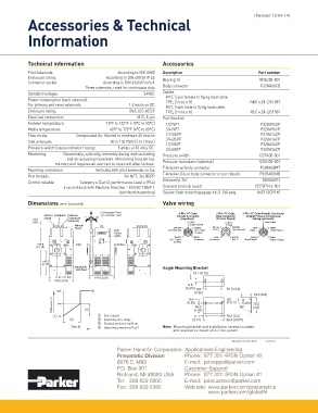
            Dimensions mm (inches)                              Valve wiring
                                        (+) Increase Time             5-Pin “A” Code  5-Pin “A” Code  5-Pin “A” Code Female Connector
                  Control  Feedback Pressure  +  (-) Decrease Time   Female Connector  Male Connector  (Digital Pressure Transducer
                           Transducer -
              16.3  Signal          5                                  (Feedback)   (Control Signal)  Wiring (optional))
              (.64)        (Optional)                                    5 GRAY         5 GRAY        5 Power Input
                              Manual                                      (Equip Ground)  Reset
                              Reset                                 BROWN  1  2 WHITE  WHITE  2  1 BROWN  Input  1  2 Digital
                                             LED                  (+24 Volts DC)  (N.O. Status  (Sol 2)  (+24 Volts DC)  Power +  Output Signal
                                             Status                         Contact)
                                       SOL.1 SOL.2 RESET  STATUS
                                        SOL
                                             Lights
                                                                    BLACK  4  3 BLUE  BLUE  3  4 BLACK  Analog  4  3 Digital
                                                                   (N.C. Status  (Common)  (Common)  (Sol 1)  Output Signal  Output 2 Signal
                                                                    Contact)
               273.8          Inlet           Outlet
               (10.78)
                 145.5
                 (5.73)
                              Adjustable                        Angle Mounting Bracket
                              Soft Start
                                                                           19.1 (0.75)
                        41.3 (1.63)  147.6 (5.81)
                      136.0 (5.35)
                                                                         9.5
                                                                        (0.375) 8.6     81.3 (3.2)
                       100%                                                 (0.34)
                                                                                                   76.2 (3.0)
                                                                          6.4           8X    R
                       60%                                               (0.25)         R 0.13   0.063  76.2
                                                                            46.2             90°  (3.0)
                                                                            (1.82)
                        0%             1  Start signal                      11.1        76.2 (3.0)
                                       2  Switching time delay             (0.44)       98.4 (3.875)
                                       3  Gradual pressure build up
                                       4  Operating pressure p 2  (=p 1 )  Note:	 Mounting bracket and installation screws included
                                                                    and required to install unit in the system.
                                                                                          Bulletin 0700-B13          4/2014
                                              Parker Hannifin Corporation Applications Engineering
                                              Pneumatic Division        Phone:  877 321 4PDN Option #2
                                              8676 E. M89               E-mail:  pdnapps@parker.com
                                              P.O. Box 901              Customer Support
                                              Richland, MI 49083 USA    Phone:  877 321 4PDN Option #1
                                              Tel:  269 629 5000        E-mail:  pdncustsvc@parker.com
                                              Fax:  269 629 5385        Web site: www.parker.com/pneumatics
                                                                                 www.parker.com/globalfrl
   1   2   3   4   5   6