
Page 5 - Parker - Flow Control Valves
P. 5
Catalog HY15-3502/US
Technical Tips Flow Control Valves
CV
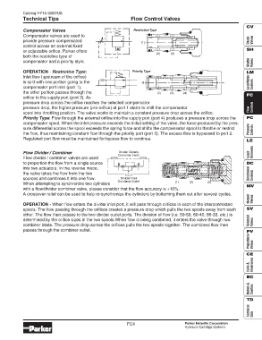
Compensator Valves Restrictive Type
Compensator valves are used to
provide pressure compensated Check Valves
(1)
control across an external fixed
SH
or adjustable orifice. Parker offers
(2) (3)
both the restrictive type of
Shuttle Valves
compensator and a priority style.
OPERATION - Restrictive Type: Priority Type LM
Inlet flow (upstream of the orifice)
is split with one portion going to the (1) Load/Motor Controls
compensator port inlet (port 1),
the other portion passes through the (2) (3) (4) FC
orifice to the supply port (port 3). As
pressure drop across the orifice reaches the selected compensator
pressure drop, the higher pressure (pre-orifice) at port 1 starts to shift the compensator Flow Controls
spool into throttling position. The valve works to maintain a constant pressure drop across the orifice.
Priority Type: Flow through the external orifice into the supply port (port 4) produces a pressure drop across the PC
compensator spool. When the inlet pressure exceeds the initial setting of the valve, the force produced by the pres-
sure differential across the spool exceeds the spring force and shifts the compensator spool to throttle or restrict Pressure Controls
the flow, thus maintaining constant flow through the priority port (port 3). The excess flow is bypassed to port 2.
Regulated port flow must be maintained for bypass flow to continue.
LE
Flow Divider / Combiner Divider Outlets Elements
Combiner Inlets Logic
Flow divider / combiner valves are used
to proportion the flow from a single source DC
into two actuators. In the reverse mode,
the valve takes the flow from the two Directional Controls
sources and combines it into one flow. Divider Inlet
Combiner Outlet (1) (2) (3)
When attempting to synchronize two cylinders
MV
with a flow/divider combiner valve, please consider that the flow accuracy is +10%.
A crossover relief can be used to help re-synchronize the cylinders by bottoming them out after several cycles.
Manual Valves
OPERATION - When flow enters the divider inlet port, it will pass through orifices in each of the interconnected
spools. The flow passing through the orifices creates a pressure drop which pulls the two spools away from each SV
other. The flow then passes to the two divider outlet ports. The division of flow (i.e. 50-50, 60-40, 66-33, etc.) is
determined by the orifice sizes in the two spools.When flow is being combined, it enters the valve through two Solenoid Valves
combiner inlets. The pressure drop across the orifices pulls the two spools together. The combined flow then
passes through the combiner outlet. PV
Proportional Valves
CE
Coils & Electronics
BC
Bodies & Cavities
TD
Technical Data
FC4 Parker Hannifin Corporation
Hydraulic Cartridge Systems