
Page 50 - Parker - Flow Control Valves
P. 50
Catalog HY15-3502/US Flow Divider/Combiner Valve
Technical Information Series L1A300
CV
General Description
Spool Type, Flow Divider/Combiner Valve. For
additional information see Technical Tips on
Check
Valves
SH pages FC1-FC4.
(4)
Features
Valves
Shuttle
LM • Interlocking spools for equal control dividing or combining
• Range of flow settings available for optimising control (3)
• Pressure compensated control in both directions
• 50/50 ratio standard, other ratios available on request Divider Outlets
Controls
Load/Motor
FC • Commonly used for differential lock in transmission Combiner Inlets
applications (2) (4)
(2)
• Hardened working parts for maximum durability
• All external parts zinc plated
Flow
Controls
PC
(3)
Divider Inlet
Combiner Outlet
(1) Plug
Controls
Pressure
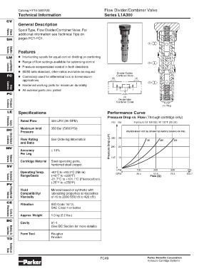
LE Specifications Performance Curve
Pressure Drop vs. Flow (Through cartridge only)
Rated Flow 320 LPM (85 GPM)
PSI Bar Hydraulic Oil 150 SSU @ 100°F (32 cSt)
Elements
Logic
Maximum Inlet 350 Bar (5000 PSI)
DC
Pressure VALVES MUST NOT BE OPERATED ABOVE 28 BAR (400 PSI)
P)
400 28
Flow Rating See Ordering Information 150 230 320
and Ratio
Directional
Controls
MV Pressure Drop ( 290 20
Accuracy ± 10%
Per Leg 145 10
Cartridge Material Steel operating parts,
Manual
Valves
hardened steel poppet.
SV
0
LPM 100 200 300 400
Operating Temp. -40°C to +93.3°C (Nitrile) 0
GPM 26.4 52.8 79.3 105.7
Range/Seals (-40°F to +200°F) Flow (Q)
-31.7°C to +121.1°C (Fluorocarbon)
Valves
Solenoid
(-25°F to +250°F)
PV
Fluid Mineral-based or synthetic with
Compatibility/ lubricating properties at viscosities
Viscosity of 45 to 2000 SSU (6 to 420 cSt)
Valves
Proportional
CE
Filtration ISO Code 16/13,
SAE Class 4 or better
Approx. Weight 1.0 kg (2.2 lbs.)
Electronics
Coils &
BC
Cavity 91-1
(See BC Section for more details)
Form Tool Rougher
Bodies &
Cavities
Finisher
TD
Data
Technical
FC49 Parker Hannifin Corporation
Hydraulic Cartridge Systems