
Page 3 - Parker - Transair: Advanced air pipe system
P. 3
1. Before installing Transair, a responsible
Transair technology person should check that the area of
installation conforms to regulations
(in particular the risks associated with
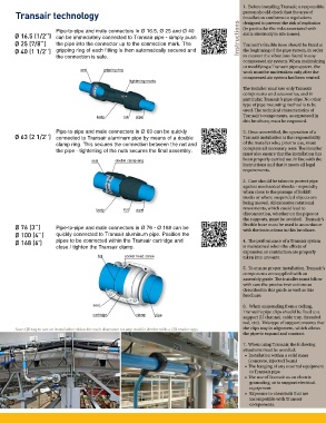
Pipe-to-pipe and male connectors in Ø 16.5, Ø 25 and Ø 40 designed to prevent the risk of explosion
Ø 16.5 (1/2’’) can be immediately connected to Transair pipe - simply push Instructions static electricity in silo zones).
Ø 25 (7/8’’) the pipe into the connector up to the connection mark. The Transair’s flexible hose should be fitted at
Ø 40 (1 1/2’’) gripping ring of each fitting is then automatically secured and the beginning of the pipe system, in order
the connection is safe. to counter the vibrations found in any
compressed air system. When maintaining
or modifying a Transair pipe system, the
seal gripping ring
work must be undertaken only after the
compressed air system has been vented.
tightening marks
The installer must use only Transair
components and accessories, and in
particular, Transair’s pipe clips. No other
type of pipe mounting method is to be
used. The technical characteristics of
body nut pipe Transair’s components, as expressed in
this brochure, must be respected.
Pipe-to-pipe and male connectors in Ø 63 can be quickly 2. Once assembled, the operation of a
Ø 63 (2 1/2’’) connected to Transair aluminum pipe by means of a double Transair installation is the responsibility
clamp ring. This secures the connection between the nut and of the installer who, prior to use, must
the pipe - tightening of the nuts secures the final assembly. complete all necessary tests. The installer
must also ensure that the installation has
seal double clamp ring been properly carried out in line with the
instructions and that it meets all legal
requirements.
3. Care should be taken to protect pipe
against mechanical shocks – especially
when close to the passage of forklift
trucks or where suspended objects are
being moved. All excessive rotational
body nut pipe movements, which could lead to
disconnection, whether on the pipes or
the supports, must be avoided. Transair’s
Ø 76 (3’’) Pipe-to-pipe and male connectors in Ø 76 - Ø 168 can be flexible hose must be used in accordance
with the instructions in this brochure.
Ø 100 (4’’) quickly connected to Transair aluminum pipe. Position the
Ø 168 (6’) pipes to be connected within the Transair cartridge and 4. The performance of a Transair system
close / tighten the Transair clamp. is maintained when the effects of
expansion or contraction are properly
lug socket head screw taken into account.
5. To ensure proper installation, Transair’s
components are supplied with an
assembly guide. The installer must follow
with care the precise instructions as
described in this guide as well as this
brochure.
seal 6. When suspending from a ceiling,
Transair’s pipe clips should be fixed to a
cartridge clamp pipe
support (U channel, cable tray, threaded
rod, etc). This type of support ensures that
Scan QR tag to see an installation video for each diameter on any mobile device with a QR reader app. the clips stay in alignment, which allows
the pipe to expand and contract.
7. When using Transair, the following
situations must be avoided:
• Installation within a solid mass
(concrete, injected foam)
• The hanging of any external equipment
to Transair pipe
• The use of Transair as an electric
grounding, or to support electrical
equipment
• Exposure to chemicals that are
incompatible with Transair
components.