
Page 11 - Gast Compressor Air and Vacuum Systems Catalog
P. 11
Technical Data
Sizing a Vacuum Receiver Vacuum Forming Work sheet
To understand tank sizing for a desired level of vacuum, it is To set up a proper vacuum forming system we must:
important to remember that the volume of the tank vs. the volume 1. Calculate the volume of the cavity(ies) to be evacuated.
of the mold will determine your system vacuum. 2. Calculate the volume of the plumbing.
3. Determine the proper receiver (tank) size.
Example: Let’s assume that for each inch of mercury we have 4. Determine the proper vacuum for the application.
one “super molecule”, and we have a tank that is 1 cubic foot
and a mold that is 1 cubic foot. All of these factors are interrelated and demand equal consider-
ation in the final system design. This work sheet is designed to
At sea level the barometric pressure is 29.92 inHg absolute (0 help you through these considerations in a step-by-step fashion.
gauge). Due to variations in the atmospheric pressure, we can
safely assume that 30 inHg is a good round number. So, at sea The next step is usually easy for a vacuum former because they
level we can say that the atmosphere has almost 30 “super mol- know the area of the mold. Some simple reminders for volume
ecules.” calculations are:
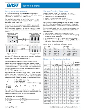
1 cubic foot Tank 10 inHg 1 cubic foot Mold 30 inHg 1. Volume is always surface area times depth (height).
absolute pressure absolute pressure 2. Volume of squares or rectangles are calculated by multiplying
(20 inHg gauge vacuum) (0 inHg gauge vacuum)
length times height times width.
3. Surface area of a circle is Pi x radius or 3.14 times radius .
2
2
4. Volume of a sphere is calculated by multiplying 4/3 Pi x R or in
3
other words, 4.189 times Radius .
3
Cubic Feet for 10-foot Section of Schedule 40 pipe
Now, we open up the valve and what happens? It balances
Pipe Inside Pipe Inside
Size Dia. Volume Size Dia. Volume
1/8” .269 .004 cu ft 3/4” .824 .037 cu ft
1/4” .364 .007 cu ft 1” 1.049 .06 cu ft
3/8” .493 .013 cu ft 1 1/2” 1.610 .14 cu ft
20 "super molecules" 20 "super molecules"
(10 inHg gauge) (10 inHg gauge) 1/2” .62 .021 cu ft 2” 2.067 .23 cu ft
Now, with an average of 20 molecules per cubic foot, our system
vacuum is 30 - 20 = 10 inHg gauge vacuum.
Reference Dimensions (inches)
If we double the size of the vacuum tank, we now have an
average of 10 super molecules in two cubic feet and 30 super Plumbing
molecules in the one cubic foot mold. So, we have 10 + 10 + 30 Overall L W Connection
= 50 super molecules in 3 total cubic feet, or 17 super molecules Model Length Height Width Length Width Hole All Female
per cubic foot, relating back to our new vacuum gauge reading, ROA-P206T 19 18 8 10 4 3/8 1/4
30 - 17 = 13 inHg gauge vacuum. DOA-P706T 18 15 8 10 4 3/8 1/4
1HAB-11T 18 17 8 10 4 3/8 1/4
Now that we understand this concept, here is a simple tank cal- 1LAA-11T 18 17 8 10 4 3/8 1/4
culation based upon Boyles Law of P V = P V . If we have a tank 2HAH-11T 18 18 8 10 4 3/8 1/4
2
1
1
2
that we are going to pump down to 25 inHg and we need a total 3HEB-11T 26 25 14 16 12 7/16 1/4
system vacuum of 20 inHg, we can do the following calculation: 4HCC-11T 33 27 16 18 14 9/16 1/4
5HCD-11T 33 27 16 18 14 9/16 1/4
D D = Desired Mold Vacuum inHg 6HCA-11T 38 29 17 22 15 9/16 3/8
T - D T = Tank Vacuum inHg 7HDD-11T 38 29 17 22 15 9/16 3/8
R = Tank to Mold Ration or Tank Volume: Mold volume (1) 8HDM-11T 38 29 17 22 15 9/16 3/8
So: 20 20 0523-V 21 17 10 10 4 3/8 1/4
D = 20 inHg 25 - 20 = R, 5 = R, 4:1 = R 1023-V 39 30 22 22 15 9/16 1 1/4
T = 25 inHg 2565-V90 40 35 24 24 15 9/16 1 1/4
We need a 4:1 ratio between the tank volume and the mold vol- 4HCC-89 48 35 38 26 18 1/2 9/16 1/2
ume. This means if the mold is 1 gallon, the tank must be at least 5HCD-95 48 35 38 26 18 1/2 9/16 1/2
4 gallons to reach the level of 20 inHg instantaneously. 6HCA-15 48 35 38 26 18 1/2 9/16 1/2
7HDD-69D 48 35 38 26 18 1/2 9/16 1/2
8HDM-30D 48 35 38 26 18 1/2 9/16 1/2
Other tank to mold volume ratios: 2565-V93 49 36 37 26 18 1/2 9/16 1 1/4
D = 15 inHg D = 22 inHg 6066-V113 50 48 34 26 18 1/2 9/16 1 1/4
T = 25 inHg T = 25 inHg 71R640-P64T- 26 23 13 16 12 7/16” 1/4”
1.5:1 7.5:1 71R640-P67T- 26 24 13 16 12 7/16” 1/4”
12
1/4”
7/16”
23
26
14
16
71R640-P65DT-
www.gastmfg.com Gast Compressed Air and Vacuum Systems 11