
Page 9 - Proportion-Air - QBT Electro-Pneumatic Pressure Reglators
P. 9
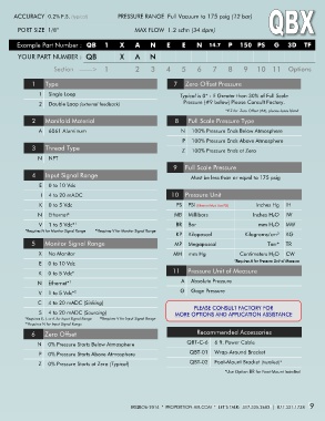
ACCURACY  0.2% F.S. (typical)          PRESSURE RANGE  Full Vacuum to 175 psig (12 bar)

        PORT SIZE  1/8”                             MAX FLOW  1.2 scfm (34 slpm)


       Example Part Number :  QB        1     X     A     N     E     E    N  14.7  P  150  PS          G  3D  TF
        YOUR PART NUMBER :  QB                X     A     N

                     Section   ——>      1           2     3     4    5     6     7     8     9  10  11  Options


             1    Type                                            7  Zero Offset Pressure
                1    Single Loop                                     Typical is 0* - If Greater than 30% of Full Scale

                2    Double Loop (external feedback)                  Pressure (#9 below) Please Consult Factory.
                                                                                      *If Z for  Zero Offset (#6), please leave blank
             2  2   Manifold Material ifold Material               8  8   Full Scale Pressure Type ll Scale Pressure Type
                  Man
                                                                        Fu
                                                                     N    100% Pressure Ends Below Atmosphere     100% Pressure Ends Below Atmosphere
                A
                A    6061 Aluminum     6061 Aluminum                 N
                                                                      P    100% Pressure Ends Above Atmosphere     100% Pressure Ends Above Atmosphere
                                                                      P
                  Th
             3  3   Thread Type read Type                             Z    100% Pressure Ends at Zero     100% Pressure Ends at Zero
                                                                      Z
               N    NPT     NPT
               N
                                                                  9  Full Scale Pressure   Full Scale Pressure
                                                                  9
                  In
             4  4   Input Signal Range put Signal Range
                                                                          Must be less than or equal to 175 psig Must be less than or equal to 175 psig
                E
                E    0 to 10 Vdc     0 to 10 Vdc
                                                                  10  Pressure Unit   Pressure Unit
                I I    4 to 20 mADC     4 to 20 mADC              10

                                                                                                  I
                K    0 to 5 Vdc     0 to 5 Vdc                      PS    PSI (Ethernet Must Use PSI) PS    PSI (Ethernet Must Use PSI)   Inches Hg    IH nches Hg    IH
                K
               N    Ethernet*     Ethernet*
                                                                   MB
               N                                                   MB    Millibars     Millibars   I Inches H 2O    IW nches H 2O    IW
                                                                                                  m
                                                                   BR
                V    1 to 5 Vdc*      1 to 5 Vdc*                  BR    Bar     Bar              mm H 2O    MW m H 2O    MW
                             1 1
                V
                                     * Requires V for Monitor Signal Range
           *Requires N for Monitor Signal Range
           *Requires N for Monitor Signal Range   * Requires V for Monitor Signal Range
                                     1 1
                                                                   KP
                                                                                             Kilo
                                                                   KP    Kilopascal     Kilopascal   Kilograms/cm²    KG grams/cm²    KG
                  Mon
             5  5   Monitor Signal Range itor Signal Range         MP    Megapascal     Megapascal    To
                                                                                                      Torr*    TR rr*    TR
                                                                   MP
                X
                X    No Monitor     No Monitor                    MH    mm Hg     mm Hg    Cent
                                                                                           Centimeters H 2O    CW imeters H 2O    CW
                                                                  MH
                                                                                         *Requires A for Pressure Unit of Measure
                E    0 to 10 Vdc     0 to 10 Vdc                                         *Requires A for Pressure Unit of Measure
                E
                                                                  11  Pressure Unit of Measure   Pressure Unit of Measure
                K    0 to 5 Vdc*     0 to 5 Vdc*                  11
                K
                                                                     A
               N    Ethernet*      Ethernet*
               N           1 1                                       A    Absolute Pressure     Absolute Pressure
                                                                     G
                             2 2
                V
                V    1 to 5 Vdc*      1 to 5 Vdc*                    G    Gage Pressure     Gage Pressure
               C
               C    4 to 20 mADC (Sinking)     4 to 20 mADC (Sinking)
                S
                S    4 to 20 mADC (Sourcing)      4 to 20 mADC (Sourcing)
                                       2 2
                                      *
          *Requires E, I, or K for Input Signal Range Requires E, I, or K for Input Signal Range   * Requires V for Input Signal Range Requires V for Input Signal Range
          *
          * * Requires N for Input Signal Range Requires N for Input Signal Range
           1 1
                                                                           R
                  Zero Offset ero Offset
             6  6   Z                                                      Recommended Accessories ecommended Accessories
                                                                       QB
               N
               N    0% Pressure Starts Below Atmosphere     0% Pressure Starts Below Atmosphere   QBT-C-6    6 ft. Power Cable T-C-6    6 ft. Power Cable
                                                                        QB
                P
                P    0% Pressure Starts Above Atmosphere     0% Pressure Starts Above Atmosphere   QBT-01    Wrap-Around Bracket T-01    Wrap-Around Bracket
                                                                        QBT-02    Foot-Mount Bracket (Installed)* T-02    Foot-Mount Bracket (Installed)*
                Z    0% Pressure Starts at Zero (Typical)     0% Pressure Starts at Zero (Typical)
                Z                                                       QB
                                                                                      *Use Option BR for Foot-Mount Installed  Use Option BR for Foot-Mount Installed
                                                                                      *
                                                                          LET’S TALK 317-335-2602   *   PROPORTION-AIR   *   BRQB041406E   9
                                                  BRQBO6-2014  *  PROPORTION-AIR.COM  *  LET’S TALK:  317.335.2602  |  877.331.1738    9