Page 6 - Parker - PGP/PGM600 Series
P. 6

Catalog HY09-600/US                               PGP/PGM600 Series
            Ordering Code                                     Heavy-Duty Cast Iron Pumps and Motors

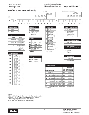
            PGP/PGM 610 How to Specify
                                                             Omit for Tandem          Repeat As Necessary For Multiple Sections
                                                                                                       Omit For
                                                                 Omit for Pumps                       Middle Section
                                                 Side   Side   Rear   Rear                    Side   Side   Rear   Rear   Omit
             Gear                                Inlet   Outlet   Inlet   Outlet             Suction  Pressure  Suction  Pressure  For Last
            Design                                Port  Port  Port  Port                      Port  Port  Port  Port  Section
              PG      610                                                    610           X
                 1        2   3   4   5   6   7   8   8   8   8   9   10   11     12   3   7   8   8   8   8   11


             1 Pump/Motor                4 Rotation             7 Shaft Seal*             9 Motor Drain Option
             P	  Pump                    C	 Clockwise           X	 No seal                B1	 No drain
             M	  Motor                   A	 Counter clockwise   N	 NBR (Buna-N)           A   SAE-4, straight
                                         B	 Bi-directional         (pump only)               thread o-ring
                                           (Motor Only)
             2 Unit                                             V	 FPM, FKM               C   SAE-6, straight
                                                                   (Fluorocarbon)            thread o-ring
                  Pump	     Motor         5 Shaft*                 (pump only)
             A	  Single unit   Standard Motor                   M	 Double NBR
                          w/o checks      A1	 9T, SAE "A" spline     (Buna-N)             10 Motor Drain Position
             B	 Multiple unit  Standard Motor   C1	 11T, SAE 19-4 spline     (pump only)  4	  Rear drain
                         w/ two checks                          W	 Double FPM
             C	    —     Standard Motor    D1	 13T, SAE "B" spline       (Fluorocarbon)
                                                                   (pump only)
                           w/one anti     K1	 32L, SAE "A" parrallel                      11 Inlet Options
                           cavitation     L6	 32L, SAE "19-1"   H	 High Pres.(7bar)            (Multi Section Units Only)
                          check (ACC)        parrallel             (motor only)           C	  Common
                                          *See	Note	1           *See	Note	2               S	  Separate
             3 Displacement
             0070   7 cc/rev                                                              12 Multiple Unit
                         3
                    (0.43 in /rev)        6 Flange
             0100   10 cc/rev                                                             A	  Last section
                    (0.61 in /rev)        H2	 SAE "A" 2-bolt                              B	  Middle section
                         3
             0140   14 cc/rev             H3	 SAE "B" 2-bolt
                         3
                    (0.85 in /rev)
             0160   16 cc/rev
                    (0.98 in /rev)                               8 Port Options*
                         3
             0180   18 cc/rev                                  	 	  	                    	    Available
                    (1.10 in /rev)                             	 	  	                   Rear	 Displacements
                         3
             0210   21 cc/rev                                  	 Code	 Description	     Ports	 for	Side	Ports
                    (1.28 in /rev)                             	 B1	 No ports           n/a   7 thru 32 cc
                         3
             0230   23 cc/rev                                  	 D3	 SAE-8 straight thread o-ring   Yes   7 thru 32 cc
                    (1.40 in /rev)                             	 D4  SAE-10 straight thread o-ring  Yes   7 thru 32 cc
                         3
             0260   26 cc/rev                                  	 D5  SAE-12 straight thread o-ring  Yes   7 thru 32 cc
                    (1.59 in /rev)                             	 D6  SAE-16 straight thread o-ring   No   7 thru 32 cc
                         3
             0280   28 cc/rev                                  	 D7	 SAE-20 straight thread o-ring   No   14 thru 32 cc
                    (1.71 in /rev)                             	 S1	 ½" Split Flange, SAE Code 61   No   7 thru 32 cc
                         3
             0320   32 cc/rev                                  	 S2	 ¾" Split Flange, SAE Code 61   No   7 thru 32 cc
                    (1.95 in /rev)                             	 S3	 1" Split Flange, SAE Code 61   No   14 thru 32 cc
                         3
                                                               	 S4	 1¼"	Split Flange, SAE Code 61  No   14 thru 32 cc
                                                               *See	Note	3
            Notes:
            1. See shaft load capacity table, page 14, to check shaft strength.
            2. Specify “V” or “W” code if phosphate ester fluid is used or
              if operating temperatures exceed  80°C (176°F).
            . See page 16 for recommended maximum flows.


                                                              6                        Parker Hannifin Corporation
                                                                                       Gear Pump Division
                                                                                       Kings Mountain, North Carolina USA
   1   2   3   4   5   6   7   8   9   10   11