Page 11 - Proportion-Air - QPV & MPV Proportional Pressure Control Valves
P. 11

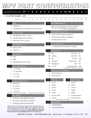
Example Part Number :  MPV  1         D    B     N     E    E     Z    0     P  150  PS  G         A    X     L


        YOUR PART NUMBER :  MPV
                     Section   ——>     1    2     3    4     5    6     7    8     9   10  11  12  13  14  15


             1    Type                                           8    Zero Offset Pressure
                1    Single Loop                                      Typical is 0* - If Greater than 30% of Full Scale
                2    Double Loop (external feedback, Requires Option 3D)   Pressure (#9 below) Please Consult Factory.
                                                                                     *If Z for  Zero Offset (#6), please leave blank
                                                                 9   Full Scale Pressure Type
             2    Mounting Type
                                                                   N    0% Pressure Ends Below Atmosphere
               D    DIN Rail Mount (Ports on Face)
                                                                   P    0% Pressure Ends Above Atmosphere
               M    Manifold Mount (Ports on Bottom)
                                                                   Z    0% Pressure Ends at Zero
                P    Panel Mount (Ports on Face)

                                                                10  Full Scale Pressure
             3    Manifold Material
                                                                          Must be less than or equal to 150 psig*
               B    Brass (Typical)
               A    Aluminum                                     11  Pressure Unit


             4    Thread Type                                       PS    PSI                    Inches Hg    IH
                                                                  MB    Millibars               Inches H 2O    IW
               N    NPT
                                                                  BR    Bar                       mm H 2O    MW
                P    BSPP
                                                                  KP    Kilopascal           Kilograms/cm²    KG
               H    Manifold Mount (No Threads)
                                                                  MP    Megapascal                   Torr*    TR
             5    Input Signal Range                              MH    mm Hg              Centimeters H 2O    CW
                                                                                        *Requires A for Pressure Unit of Measure
               E    0 to 10 Vdc
                                                                 12  Pressure Unit of Measure
                I    4 to 20 mADC
                                                                   A    Absolute Pressure
               K    0 to 5 Vdc
                                                                   G    Gage Pressure
               V    1 to 5 Vdc
                                                                13  Inlet Valve            14  Exhaust Valve
                                                                               1
                                                                                                             1
             6   Monitor Signal Range
                                                                   A    0.013”               A    0.013”*
               X    No Monitor
                                                                   B    0.025”               B    0.025”*
               E    0 to 10 Vdc
                                                                   C    0.040”               C    0.040”*
               K    0 to 5 Vdc*
                                                                   D    0.060”               D    0.060”*
                           1
               V    1 to 5 Vdc*
                                        1
           *Requires E, I, or K for Input Signal Range   * Requires V for Input Signal Range   E    0.089”   E    0.089”*
             7   Zero Offset                                       N    No Inlet Valve*      N    No Exhaust Valve
               N    0% Pressure Starts Below Atmosphere            X    0.040”*              X    0.040” (Typical)
                                                                            *Vacuum Pressure Units Only
               P    0% Pressure Starts Above Atmosphere
                                                                15  Bleed Orifice
                                                                                  2
               Z    0% Pressure Starts at Zero (Typical)
                                                                   N    No Bleed Orifice
           ¹ Inlet valves orifice size and the exhaust valve are factory determined based on the
           application’s flow and pressure specs. ² Bleed orifice is required when the QPV is   L    Include Bleed Orifice
           used in an application that is static (no flow). Dynamic applications (under flow) do
             not need a bleed orifice to function properly. Consult our Application Engineering
           Department for your specific application needs.  We are here to help you.
                         BRQPVMPV-201606A  *  PROPORTIONAIR.COM  *  LET’S TALK - 317.335.2602  |  877.331.1738     1 1
   6   7   8   9   10   11   12