Page 44 - Clippard - Electronic Valves
P. 44

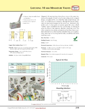
LATCHING 10 MM MINIATURE VALVES


                                  • 2-Way & 3-Way Normally-Closed   Clippard’s 10 mm Latching Valves have many of the same fea-
                                   configurations           tures as the popular 10 mm valve line including small, compact
                                  • Pulse-actuated (on or off)  design, exceptional life and reliability, light-weight design and
                                  • Polarity reverse required  more. A careful balance of forces—through the precise place-
                                  • Stable latch            ment of a permanent magnet in the valve core—produces a bi-
                                                            stable valve. A short pulse of current opens the valve, which
                                                            “latches” open indefinitely after the current stops. A subsequent
                                                            pulse of current in the opposite  direction closes the valve. The
                                0.71                        valve consumes less energy and produces less heat than a stan-
                                                            dard solenoid valve when used in extended duty cycle applica-
                       M1.7                                 tions, since the coil is energized for only a small fraction of the
              1.08     x 0.35                               total duty cycle.
                                              0.24
                                                            Max. Flow Rate:  31.2 l/min

              0.39                                          Working Pressure: 0 to 110 psig                RoHS
                        0.08        0.51      0.26
                                                            Orifice: 0.030”
              Copper Wire Isolation Class: F 311°F          Electrical Connection:  2-Wire Reverse Polarity, 300 mm, 24 AWG
              Material:  Stainless steel core and springs, nylon body, FKM   Electrical: 12  VDC (“-012”)  or 24 VDC (“-024”). 6 VDC also
                dynamic seals, and Nitrile gasket and static seals.   available. Call for further information.

              Temperature Range:  23 to 122°F. When below   Electrical Tolerance: -5 to +10%
                32°F, must use clean, dry air
                                                            Response Time:  8 ms when energized; 10 ms when de-energized
              Medium:  Air, Gas or other Compatible Fluids
                                                            Connector: Wire Leads

                                                                                 Typical Air Flow
                                                                        40
                                                                       (1.4)
                 Type         Part No.                       Voltage       Wattage       35
                                                                       (1.2)
                                                                                                      E3L10C
                                                                        30
                                       E2L10C-7W012               12 VDC   2.0  (1.1)
                2-Way
                                       E2L10C-7W024               24 VDC   25
                                                                      Flow, slpm (scfm)  (0.7)
                                       E3L10C-7W012               12 VDC  (0.9)
                3-Way                                     2.0
                                       E3L10C-7W024               24 VDC   20
                                                                        15
                                                                       (0.5)
                                                                        10
                                                                       (0.4)
                                                                        5
                                                                       (0.2)
                                                                        0
                                                                          0    10     20    30    40     50    60     70    80    90    100   110   120
                                                                                          Pressure (psig)
                                                                                  Mounting Interface

                                                                                         COIL DIRECTION
                                                                                    0.05 dia
                                                                                    max. (3)      0.10
                                                                                     places
                                                                                                      0.10

                                                                                   M1.7 x   0.26   0.06
                                                                                    0.35
                                              See pages 224 & 227 for connectors and manifolds


            Clippard Instrument Laboratory, Inc. 877-245-6247 www.clippard.com                                218
   39   40   41   42   43   44   45   46   47   48   49