Page 121 - Joyce - Jacks, actuators and systems
P. 121

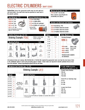
ELECTRiC CyLiNDERS ShAFT CODES


            Instructions: Select the appropriate shaft codes for both right and    Mechanical Counters (p. 177)
            left hand shafts. One shaft code must be specified for each side of    CNT0=0.001" Increments
            the electric cylinder.
                                                                          Note: Contact Joyce/Dayton for
                                                                          availability and options.
             Hand Wheels (p. 177)          Geared Potentiometers (p. 176)
             HW04=4" dia                   POTA=0-10V (IP65)
             HW06=6" dia                   POTB=4-20MA (IP65)
             HW08=8" dia                   POTC=0-10V w/2 switches*       Encoders and Electronic Limit Switches
             HW10=10" dia                  POTD=4-20MA w/2 switches*      ENCX=Encoder (p. 178)
             HW12=12" dia                  *Optional IP65                 ELS2=2 Position Electronic Switch
             Not recommended for cylinders      rating available.         ELS4=4 Position Electronic Switch
             that are ≥ 30% efficient.
                                                                          ELS6=6 Position Electronic Switch

             ComDrive Reducers (pp. 125-134)                        Motors               Motor Mounts (p. 185)
             Ordering Example: p2AC              Motor code from      Size     Code       Ordering Example:
                                                 chart at right
                                                                     1/4 HP     K         mmA A
             Mounting Positions                          Ratio       1/3 HP      A
               Code     P1       P2      P3       P4                 1/2 HP     B
                                                           5:1
               Left                                      Code A      3/4 HP     C         MMA=56C     Motor code
               Side
               Shaft                                                  1 HP      D         MMB=140TC   from chart
             Positions                                    7.5:1     1-1/2 HP     E        MMC=180TC   at left
                                                         Code B
                                                                      2 HP       F        MMD=210TC
               Right
               Side                                        10:1                           Standard motor adapters
               Shaft                                     Code C       3 HP       L
             Positions                                                                    are aluminum.
                                                                      5 HP      G
            All standard motors are 3-phase, 208-230/460 VAC or 230/460 VAC. Specify the appropriate motor size from the chart above. Refer
            to the “Additional Options” chart on the preceding page as needed.  Brake motors are required for electric cylinders that are more
            than 30% efficient.  Contact Joyce/Dayton options that are not listed.

             Mechanical Limit Switches (pp. 174-175)                                     To order additional options,
                                                                                         use these part numbers (p. 124)
                                   Ordering Example: LA13                                Female Clevis Bracket

                                                                                         FCB-30
                                                                                         FCB-100
             Models                  Available Positions                                 FCB-200
             Model  Code                          1             3             5
            LS7-402  LI                                                                  Clevis Pin w/ retaining rings
                                      Left                                               CP-30
            LS8-402  LA               Side
                          Number of    Shaft                                             CP-100
            LS8-404  LB  DPDT Switches    Options
                          (see p. 175)                                                   CP-200
            LS9-502  LC
                           NOTE:                                                         Female Rod Clevis
            LS9-503  LD  Will always be
                        0 for LS7 models  Right                                          FRC-30
            LS9-504  LE
                                      Side
                                     Shaft                                               FRC-100
            LS9-505  LF
                                     Options                                             FRC-200
            LS9-506  LG
                                   • 2.5, 3, 5, 10, and 20 Ton Electric Cylinders are available with positions
            LS9-507  LH
                                     #1, #3, and #5


                                Custom products are available • Contact Joyce/Dayton with your requirements   121
            800-523-5204                      sales@joycedayton.com                  joycedayton.com
   116   117   118   119   120   121   122   123   124   125   126