
Page 129 - Joyce - Jacks, actuators and systems
P. 129
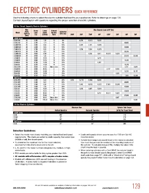
ELECTRiC CyLiNDERS QuiCK REFERENCE

            Use the following charts to select the electric cylinder that best fits your application. Refer to drawings on page 134.
            Contact Joyce/Dayton with questions regarding the proper selection of electric cylinders.

             20-Ton Thrust Capacity Electric Cylinders
                      Max    Screw    Linear    External                      Max Dynamic Load at HP (lbs)
                     Static
              Model  Capacity   Lead  Speed    Gearbox  Estimated
                                                  Efficiency
                     (tons)   (in)  (in/min)  Ratio        .33HP   .5HP   .75HP   1HP    1.5HP  2HP     3HP    5HP
             ACME Screw
             ECAL2420  20    0.250   1.76    10     8%            6,459  10,813  15,552
             ECAL2420  20    0.250   1.71    10     8%                                                 40,000
             ECAm2420  20    0.500   3.53    10     13%           5,484   9,181  13,205
             ECAm2420  20    0.500   3.42    10     14%                                                40,000
             ECAh2420  20    0.750   5.29    10     16%           4,560   7,634  10,979
             ECAh2420  20    0.750   5.13    10     17%                                                38,366
             ECAm2420  20    0.500   6.94    5      15%                   4,305  6,621  10,972  15,324
             ECAm2420  20    0.500   7.29    5      15%                                                23,176  39,948
             ECAm820  20     0.500   10.59   10     17%                          5,276
             ECAm820  20     0.500   10.25   10     18%                                                19,447
             ECAh820  20     0.750   15.38   10     22%                          4,387
             ECAh820  20     0.750   14.89   10     23%                                                16,170
             ECAL2420  20    0.250   18.23  Direct drive  11%                                           4,701  9,678
             ECAm820  20     0.500   20.83   5      19%                                  4,127  5,935
             ECAm820  20     0.500   21.88   5      19%                                                 9,218  16,187
             ECAh820  20     0.750   31.25   5      23%                                         4,935
             ECAh820  20     0.750   32.81   5      24%                                                 7,665  13,459
             Ball Screw
             ECBL2420  20    0.500   3.53    10     33%    7,425  13,710  22,953  33,012
             ECBL2420  20    0.500   3.42    10     35%                                                40,000
             ECBL2420  20    0.500   6.94    5      37%           5,442  10,763  16,553  27,431  38,309
             ECBL2420  20    0.500   7.29    5      39%                                                40,000
             ECBL820  20     0.500   10.59   10     43%           4,876   8,857  13,189
             ECBL820  20     0.500   10.25   10     45%                                                40,000
             ECBL820  20     0.500   20.83   5      47%                          5,797  10,317  14,837
             ECBL820  20     0.500   21.88   5      48%                                                23,046  40,000
             ECBL2420  20    0.500   36.46  Direct drive  49%                                   4,697
             ECBL820  20     0.500  109.38  Direct drive  55%                                                  6,665
             20-Ton Electric Cylinders
                                                            Maximum Rise                          Cylinder Tube Torque
                                              vertical Operation        Horizontal Operation     (in*lb) Per Pound Thrust
             ACME Screw
             ECAL                                 100"                      75"                       .178
             ECAm                                 78"                       58"                       .210
             ECAh                                 88"                       66"                       .244
             Ball Screw
             ECBL                                 72"                       54"                       .089

            Selection Guidelines:
            •  Select the model most closely matching your desired load and speed   •  Loads and speeds shown assume use of a 1750 rpm 3ph AC
             requirements.  The charts are sorted by static capacity, then screw type   induction motor.
             (ACME or ball), then travel speed.                   •  Cylinder tube torque per pound thrust is the means to calculate
            •  To determine the maximum rise for the model selected,    how much torque must be resisted at the mounting locations of
             see maximum rise charts above and to the left.        the cylinder.  To calculate torque (in*lb), multiply the value in the
            •  L, M, and H in the model numbers designate low, medium, or high   chart times the load in pounds.
             screw leads.                                         •  When ordering cylinders with a ComDRIVE the reducer listed in
            •  ECA models are not suitable for duty cycles greater than 25%.  the part number should specify the proper 4 letter ComDRIVE
            •  All models with efficiencies >30% require a brake motor.  shaft code from page 121. Units with a “direct drive” listing should
                                                                   specify the proper 4 letter motor mount code listed on page 121.
            •  Models with efficiencies ≤30% are self-locking in the absence
             of vibration.  A brake motor is required if vibration is present or
             faster stopping times are desired.


                              2D and 3D models available on website • Ordering information on pages 120 and 121  129
            800-523-5204                      sales@joycedayton.com                  joycedayton.com