
Page 2 - Parker - AirGuard Protection System
P. 2
AirGuard Protection System
SW *
Function: P
(P) is the inlet. Air passes the piston (1) and
continues through the seat (3). The air flow, passing
the piston, is slowed down by means of length
wise grooves on the outer side of the piston. If
the flow is too high, the air cannot pass the piston 1 A
quickly enough, and the piston is forced against A
the spring (2) and towards the seat. The maximum A B
flow is shown in the graph. If the value indicated 2
is exceeded e.g. if the hose suddenly breaks - the
air supply is automatically shut of. An integral 3
bleed hole allows some air to flow though. This
enables the line pressure to automatically reset the SW SW SW
AirGuard once the main line break is repaired. 1/4" - 3/8" - 1/2" 1/4" - 3/8" - 1/2" 3/4" - 1" - 2"
Weight and Dimensions metric (imperial)
Thread Weight Max. Inlet P1 Inlet P2 Outlet Part Number Part Number
Connection Dimensions mm (inch) g (oz.) Pressure Temp. Range Material Thread Thread NPT BSP
A B SW
1/4" 48 (1.89) - 22 (.87) 30 (1.06) Female Female P4GAA92 P4GAA12*
1/4" 58 (2.28) 49 (1.93) 22 (.87) 36 (1.27) Male Female P4GBA92 P4GBA12*
3/8" 59 (2.32) - 28 (1.10) 58 (2.05) -20°C to 80°C Housing: Aluminum Female Female P4GAA93 P4GAA13*
(18 bar)
3/8" 71 (2.80) 59 (2.32) 28 (1.10) 62 (2.19) (-4°F to 176°F) Piston: Polyacetal Male Female P4GBA93 P4GBA13*
255 PSIG
1/2" 65 (2.56) - 31 (1.22) 78 (2.75) Female Female P4GAA94 P4GAA14*
1/2" 80 (3.15) 65 (2.56) 31 (1.22) 85 (3.00) Male Female P4GBA94 P4GBA14*
3/4" 76 (2.99) - 30/36* (1.18/1.42*) 107 (3.77) Female Female P4GAA96 P4GAA16*
-20°C to 120°C Housing: Aluminum
1" 100 (3.94) - 41/50* (1.61/1.97*) 300 (10.58) Female Female P4GAA98 P4GAA18*
(35 bar) 500 PSIG (-4°F to 248°F) Piston: Aluminum
2" 130 (5.12) - 70/80* (2.76/3.15*) 775 (27.34) Female Female P4GAA9C P4GAA1C*
* Note: BSP Threads Available Upon Request.
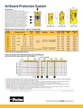
How to Select the Optimal Size of an AirGuard
Information based on an inlet pressure of 7 bar (100 PSIG)
Air Flow - l/min (SCFM)
60 120 300 600 1200 3200 6000 12000
(2.11) (4.24) (10.59) (21.19) (42.38) (113.01) (211.89) (423.78)
0 (0) 1 Hose Internal Diameter - mm (in) 6 (0.24) 8 (0.31) 10 (0.39) 13 (0.51) 16 (0.63) 20 (0.79)
2 (6.56)
4 (13.12)
Hose Length - Meters (Feet) 10 (32.80) 2 4 3
6 (19.68)
8 (26.25)
12 (39.37)
14 (45.93)
16 (52.49)
18 (59.05)
20 (65.62)
Port Size
a. Determine the internal diameter of the hose, tube or pipe being used 1 (see specification Hose-internal Diameter in yellow box, yellow diagonal line).
b. Determine the length of the hose, tube or pipe 2 (Hose length in meters).
c. Define the intersection of point a and b, and mark a vertical line downwards. 3 - 4 (In the example the red/green dot and the green dashed line).
d. The next vertical black line, left of the intersection line 4 (example: green dashed) tells the correct AirGuard size (in inches).
e. Important: Every flow value to the right of the respective vertical line (black) would activate the AirGuard in case of a bursting hose, pipe or tube.
All AirGuard sizes right of the intersection line (green) are too big and will not close up.
f. Example: Which air fuse should be used for a hose, pipe or tube bearing 8 mm inner diameter and 10 meters of length - follow the 10 meter line
(red 2 ) to the intersection point (red/green dot 3 ). Now the next left black line marks the correct size.
g. Result: The correct size in our example is the AirGuard 3/8”
© 2008 Parker Hannifin Corporation. All rights reserved. Bulletin 0700-B10 June, 2009