
Page 258 - Wagp_InterfaceElectronic_Volume4_2015_US.pdf
P. 258
789-652
4 Current Signal Conditioner for RT 500 Rogowski Coils
256
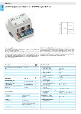
U3 I
L3
GND I
L2
OUT (I)
U2 I
L1
IN (U)
GND I
N
U1 24 V
POWER
GND 0 V
Short description: The 750-493/000-002 3-Phase Power Measurement Module within the
The Rogowski Current Signal Conditionerucer acquires 5–500A alternating WAGO-I/O-SYSTEM measures electrical data (e.g., voltages, currents, effec-
currents in a three-phase system. tive power and energy consumption) in a three-phase supply network. Thus,
The magnetic field produced around each conductor is sensed via three non- the user is always able to determine the load condition (imbalance, capacitive
contact Rogowski coils and provided as a proportional voltage signal to the components), to optimize consumption and protect machines or systems from
signal conditioner. The current signal conditioner adjusts the phase of each of damage and breakdowns. Easy installation of Rogowski coils also allows exis-
the three voltage signals, converting them into 100mA alternating current sig- ting systems to be retrofitted without process interruption.
nals. These are then transmitted to the 750-493/000-002 3-Phase Power
Measurement Module.
Description Item No. Pack. Technical Data
Unit
Signal Conditioner for RT 500 Rogowski 789-652 1 General specifications:
Coils Supply voltage range 16.8 ... 32 V
Max. power consumption 4000 mW
Operational indication LED, green
Degree of protection IP20
Phase error < 1°
Max. operating frequency 300 Hz (phase accuracy at 50 Hz only)
Linearity ≤ 0.1 %
Accessories Item No. Pack. Temperature coefficient ≤ 0.1 %/K
Unit Transmission error < 1.1 %
Rogowski Coil RT 500, Response threshold 2 A
1.5 m output cable 855-9100/500-000 3 Environmental requirements:
Rogowski Coil RT 500, Ambient operating temperature -25 °C ... +70 °C
3 m output cable 855-9300/500-000 3 Storage temperature -40 °C ... +85 °C
3-Phase Power Measurement Module Safety and protection:
(480V/1A) 750-494 1 Test voltage
(input/output/supply) 2.5 kV AC, 50 Hz, 1 min.
Connection and type of mounting:
Technical Data Wire connection CAGE CLAMP ®
Cross sections 0.08 mm² ... 2.5 mm² / AWG 28 ... 12
Input: Strip lengths 5 ... 6 mm / 0.22 in
Input signal 3 x RT500 (500 A) Dimensions and weight:
Sensitivity 10.05 mV Dimensions (mm) W x H x L 70 x 55 x 90
50 Hz sinus Weight 128.4 g
Outputs: Standards and approvals:
Output signal 3 x 100 mA AC Conformity marking 1
Rated output current 100 mA AC (for direct connection to r UL 508 (pending)
750-493/000-002 Phase Power
Measurement Module)
Overcurrent 750 A (max. 150 mA per output)