
Page 286 - Wagp_InterfaceElectronic_Volume4_2015_US.pdf
P. 286
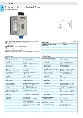
787-850

   5    Switched-Mode Power Supply, 3-Phase

                ®
  284   EPSITRON  PRO Power


                                                                                          S1 S2  S3 S4  RS-232
                                                                                       L1
                                                                                       L2           DC+
                                                                                                    DC+
                                                                                       L3           DC -
                                                                                                    DC -


        • Primary switch mode power supply unit with PowerBoost and TopBoost                              Pack.
        • LineMonitor for parameter setting and monitoring    Description                  Item No.       Unit
        • RS-232 serial interface                             Switched-Mode Power Supply,   787-850       1
        •4 signal outputs                                     24 V DC / 10 A
        • Parallel operation, series connection possible
        • Prepared for class I equipment
        • Natural convection cooling when horizontally mounted
        • Enclosed for use in switchgear cabinets
        • Electrically isolated output voltage (SELV) acc. to EN 60950-1/UL 60950

        Technical Data                                        Technical Data

        Input:                                                Environmental requirements:
          Nominal input voltage Vi nom  3x (2x) 400 ...  500 VAC  Ambient operating temperature  -25 °C ... +70 °C
          Input voltage range     340 ... 550 VAC; 480 ... 780 VDC  Storage temperature  -25 °C ... +85 °C
          Frequency               50 - 60 Hz                    Rel. humidity          30 % ... 85 % (no condensation)
          Input current Ii        3 x 0.6 A at 340 VAC and 10 ADC  Derating            -3 % / K (> 50 °C)
          Discharge current       1 mA typ.                     Degree of pollution    2 (acc. to EN 50178)
          Inrush current          < 30 A                        Climatic category      3K3 (acc. to EN 60721)
          Mains failure hold-up time  22 ms typ. at 3 x 400 VAC  Safety and protection:
        Output:                                                 Test voltage pri.-sec./ pri.-gr. / sec.-gr.  4.2 kV DC / 2.2 kV DC / 0.7 kV DC
          Nominal output voltage Vo nom  24 VDC (SELV)          Protection class       Prepared for class I equipment
          Output voltage range    22.8 ... 28.8 VDC adjustable  Degree of protection   IP20 acc. to EN 60529
          Output current Io       10 A at 24 VDC                Overvoltage protection  via varistor at primary circuit
          PowerBoost              20 ADC (for 4 s); 15 ADC (for 16 s)  Short circuit protection  yes
          TopBoost                70 ADC (for 50 ms)            No-load proof          yes
          Factory preset          24 VDC                        Feedback voltage       max. 35 VDC
          Adjustment accuracy     1%                            Parallel operation     yes
          Residual ripple         < 70 mV (peak-to-peak)        Series connection      yes
          Current limitation      1.1 x Io typ.               Connection and type of mounting:
          Overload behavior       adjustable (constant current / fuse mode)  Wire connection  Input/Output: WAGO 231 Series
          Operational indication  LED green (DC O.K.), LED yellow                      Signalising: WAGO 733 Series
                                  (warning), LED red (error)    Cross sections         Input/Output:
          Signaling               LED, LCD, 4 x signal output 24 V DC,                 0.08 mm² ... 2.5 mm² / AWG 28 ... 12
                                  25 mA                                                Signalising:
          LineMonitor, parameter setting  via LCD and RS-232 serial interface          0.08 mm² ... 0.5  mm² /  AWG 28 ... 20
        Efficiency / power losses:                              Strip lengths          Input/Output: 8 ... 9 mm / 0.33 in
          Efficiency              91.7 % typ.                                          Signalising: 5 ... 6  mm / 0.22 in
                                  7.8 W (stand-by) / 19.9 W (rated load)  Type of mounting  DIN-rail mounting (EN 60715) in
          Power loss P V
        Fuse protection:                                                               2 positions
          Internal fuse           3 x T 1.6 A / 250 V         Dimensions and weight:
          External fuse           3 x circuit breakers 6 A, 10 A, 16 A,   Dimensions (mm) W x H x L  57 x 163 x 179
                                  characteristic: B or C;                              Height from upper-edge of DIN 35 rail
                                  or motor circuit breakers,    Weight                 1000 g
                                  setpoint: 1.6 A, setting range: 1.6 ... 2.5 A   Standards and approvals:
                                  An external DC fuse is required for the DC   Standards/Specifications  EN 60950, EN 61204-3,
                                  input voltage                                        UL 60950, UL 508