
Page 30 - Wagp_InterfaceElectronic_Volume4_2015_US.pdf
P. 30
1 Relay Sockets with Miniature Switching Relay
28
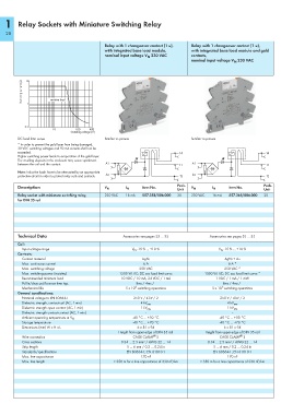
Relay with 1 changeover contact (1 u), Relay with 1 changeover contact (1 u),
with integrated base load module, with integrated base load module and gold
nominal input voltage V 230 VAC contacts,
N
nominal input voltage V 230 VAC
N
Switching current (A) 10 1 resistive load
0.1
1 10 100 400
Switching voltage (V)
DC load limit curve Similiar to picture Similiar to picture
* In order to prevent the gold layer from being damaged,
30 VDC switching voltages and 50 mA currents shall not be
exceeded.
Higher switching power leads to evaporation of the gold layer.
The resulting deposits in the enclosure may cause sparkovers
between the coil and the contact. A1 A1
Note: Inductive loads have to be attenuated by an appropriate
protective circuit in order to protect relay coils and contacts. A2 A2
Description Item No. Pack. Item No. Pack.
V N
I N
Unit V N I N Unit
Relay socket with miniature switching relay, 230 VAC 16 mA 857-358/006-000 25 230 VAC 16 mA 857-368/006-000 25
for DIN 35 rail
Technical Data Accessories see pages 33 … 35 Accessories see pages 33 … 35
Coil:
Input voltage range V N -15 % ... +10 % V N -15 % ... +10 %
Contacts:
Contact material AgNi AgNi + Au
Max. continuous current 6 A 6 A *
Max. switching voltage 250 VAC 250 VAC *
Max. switching power (resistive) 1500 VA AC; DC see load limit curve 1500 VA AC; DC see load limit curve *
Recommended minimum load 10 VDC / 10 mA, 24 VDC / 1 mA 1 VDC / 1 mA / 1 mW
Pull-in/drop-out/bounce time typ. 8ms / 4ms / - 8ms / 4ms / -
6
6
Mechanical life 5 x 10 switching operations 5 x 10 switching operations
General specifications:
Nominal voltage to EN 60664-1 250 V / 4 kV / 2 250 V / 4 kV / 2
Dielectric strength, contact-coil (AC, 1 min) 4 kV rms 4 kV rms
Dielectric strength open contact (AC, 1 min) 1 kV rms 1 kV rms
Dielectric strength contact-contact (AC, 1 min) - --
-40 °C … +50 °C -40 °C … +50 °C
Ambient operating temperature at V N
Storage temperature -40 °C … +70 °C -40 °C … +70 °C
Dimensions (mm) W x H x L 6 x 81 x 94 6 x 81 x 94
Height from upper-edge of DIN 35 rail Height from upper-edge of DIN 35 rail
®
®
Wire connection CAGE CLAMP S CAGE CLAMP S
Cross sections 0.34 … 2.5 mm² / AWG 22 … 14 0.34 … 2.5 mm² / AWG 22 … 14
Strip length 5 … 6 mm / 0.2 … 0.24 in 5 … 6 mm / 0.2 … 0.24 in
Standards/specifications EN 60664-1; EN 61810-1 EN 60664-1; EN 61810-1
Max. line capacitance 170 nF 170 nF
Max. line length > 350 m for a line capacitance of 330 nF/km > 350 m for a line capacitance of 330 nF/km