
Page 328 - Wagp_InterfaceElectronic_Volume4_2015_US.pdf
P. 328
787-1675
5 Switched-Mode Power Supply with Integrated UPS Charger and Controller
326 EPSITRON ®
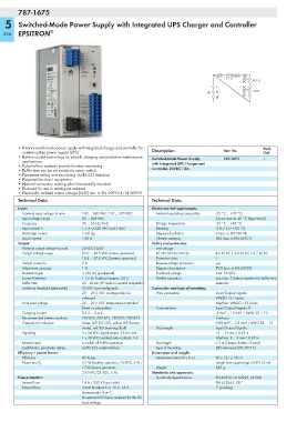
RS-232 REMOTE CTRL
DC+ ACCU
DC–
L DC+
DC+ OUT
IN N DC–
DC–
3
• Primary switch mode power supply with integrated charger and controller for Pack.
uninterruptible power supply (UPS) Description Item No. Unit
• Battery control technology for smooth charging and predictive maintenance Switched-Mode Power Supply, 787-1675 1
applications with Integrated UPS Charger and
• Potential-free contacts provide function monitoring
• Buffer time can be set on-site via rotary switch Controller, 24VDC / 5A
• Parameter setting and monitoring via RS-232 interface
• Prepared for class I equipment
• Natural convection cooling when horizontally mounted
• Enclosed for use in switchgear cabinets
• Electrically isolated output voltage (SELV) acc. to EN 60950-1/UL 60950
Technical Data Technical Data
Input: Environmental requirements:
Nominal input voltage Vi nom 100 ... 240 VAC; 110 ... 370 VDC Ambient operating temperature -25 °C ... +70 °C;
Input voltage range 85 ... 264 VAC Device start at -40 °C (type-tested)
Frequency 45 ... 65 Hz; 0 Hz Storage temperature -25 °C ... +85 °C
Input current Ii 1,1 A at 230 VAC and 5 ADC Derating -3 % / K (> +50 °C)
Discharge current 1 mA typ. Degree of pollution 2 (acc. to EN 50178)
Inrush current < 30 A Climatic category 3K3 (acc. to EN 60721)
Output: Safety and protection:
Nominal output voltage Vo nom 24 VDC (SELV) Test voltage
Output voltage range 23.0 ... 28.5 VDC (mains operation) pri.-sec./pri.-gr./sec.-gr. 4.2 kV DC / 2.2 kV DC / 0.7 kV DC
18.5 ... 27.5 VDC (battery operation) Protection class I
Output current Io 5 A Reverse voltage protection yes
Adjustment accuracy 1 % Degree of protection IP20 (acc. to EN 60529)
Residual ripple < 100 mV (peak-peak) Feedback voltage max. 35 VDC
Current limitation 1.1 x Io; TopBoost approx. 24 A Parallel operation yes, max. 3 battery modules for buffer time
Buffer time 0.5 ...20 min, IPC mode or constant (adjustable) extension
Switch-on threshold (adjustable) 22 VDC (pre-configured), Connection and type of mounting:
20 ... 25.5 VDC (configurable via Wire connection Input/Output/Signals:
software) WAGO 721 Series
Final load voltage 26 ... 29.5 VDC temperature-controlled Interface: WAGO 733 Series
(fixed or adjustable) Cross sections Input/Output/Signals: 0
Charging current 0.3 A ... 0.6 A .5 mm² ... 10 mm² / AWG 20 ... 10
Recommended battery modules 787-876, 787-871, 787-872, 787-873 Interface:
Operational indication Green LED (DC OK), yellow LED (battery 0.08 mm² ... 2.5 mm² / AWG 28 ... 12
mode), red LED (warning/fault) Strip lengths Input/Output/Signals:
Signaling 3 x 24 VDC signal output, 25 mA and 13 ... 15 mm / 0.55 in
1 x 30 VDC isolated relay contact, 1 A Interface: 8 ... 9 mm / 0.33 in
Remote input to switch off buffer operation Line length ≤ 3 m (Output, Battery Control)
LineMonitor, parameter setting via RS-232 serial interface Type of mounting DIN-rail mount (EN 60715)
Efficiency / power losses: Dimensions and weight:
Efficiency 89 % typ. Dimensions (mm) W x H x L 60 x 127 x 135.5
5.2 W (battery operation, 24 VDC, 5 A) / Length from upper-edge of DIN 35 rail
Power loss P V
17 W (mains operation, Weight 885 g
230 VAC/24 VDC, 5 A) Standards and approvals:
Fuse protection: Standards/Specifications EN 60950, UL 60950, UL 508,
Internal fuse T 4 A / 250 V (input side) EN 61204-3, GL *
External fuse Circuit breakers 6 A, 10 A, 16 A, (* pending)
characteristic: B or C;
An external DC fuse is required for the DC
input voltage