
Page 46 - Wagp_InterfaceElectronic_Volume4_2015_US.pdf
P. 46
1 Relay Sockets with Miniature Switching Relay
44
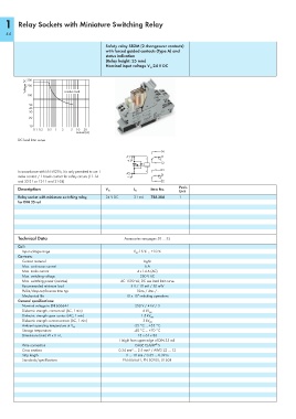
Safety relay SR2M (2 changeover contacts)
with forced guided contacts (Type A) and
status indication
(Relay height: 25 mm)
Nominal input voltage V 24 V DC
N
Voltage (V) 300
200
100 resistive load
50
40
30
20
10
0.1 0.2 0.5 1 2 5 10 20
Current (A)
DC load limit curve
In accordance with EN 50205, it is only permitted to use 1
make contact / 1 break contact for safety circuits (11-14
and 22-21 or 12-11 and 21-24)
Description Item No. Pack.
V N
I N
Unit
Relay socket with miniature switching relay, 24 V DC 31 mA 788-384 1
for DIN 35 rail
Technical Data Accessories see pages 50 … 55
Coil:
Input voltage range V N -15 % ... +10 %
Contacts:
Contact material AgNi
Max. continuous current 6 A
Max. make current 4 s 14 A (AC)
Max. switching voltage 250 V AC
Max. switching power (resistive) AC 1500 VA; DC see load limit curve
Recommended minimum load 5 V / 10 mA / 50 mW
Pull-in/drop-out/bounce time typ. 10ms / 4ms / -
Mechanical life 10 x 10 switching operations
6
General specifications:
Nominal voltage to EN 60664-1 250 V / 4 kV / 3
Dielectric strength, contact-coil (AC, 1 min) 4 kV rms
Dielectric strength open contact (AC, 1 min) 1.5 kV rms
Dielectric strength contact-contact (AC, 1 min) 3 kV eff
-25 °C ... +55 °C
Ambient operating temperature at V N
Storage temperature -40 °C ... +70 °C
Dimensions (mm) W x H x L 15 x 64 x 86
Height from upper-edge of DIN 35 rail
®
Wire connection CAGE CLAMP S
Cross sections 0.34 mm² … 2.5 mm² / AWG 22 … 12
Strip length 9 … 10 mm / 0.35 … 0.39 in
Standards/specifications EN 60664-1, EN 50205; UL 508
–