
Page 80 - Wagp_InterfaceElectronic_Volume4_2015_US.pdf
P. 80
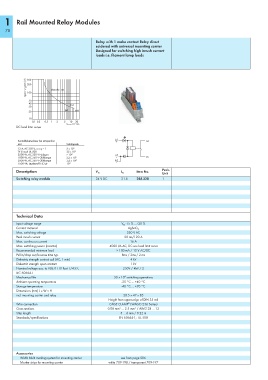
1    Rail Mounted Relay Modules


   78
                                            Relay with 1 make contact Relay direct
                                            soldered with universal mounting carrier
                                            Designed for switching high inrush current
                                            loads i.e. filament lamp loads


             Spannung DC (V)  300  ohmsche Last
             200
             100

              50
              40
              30                12A
                              8A  16A
              20
              10
               0,1 0,2   0,5  1   2   5   10  20
                              Strom DC (A)
        DC load limit curve
                                                    A1
         Kontaktlebensdauer bei Lampenlast           +            14
         Last                  Schaltspiele
         12 A, AC 250 V, cos ϕ = 1      3 x 10 5
         TV 8 nach UL 508      25 x 10 3
         2500 W, AC 230 V Halogen     > 10 4        A2
         1000 W, AC 250 V Glühlampe   2,3 x 10 5     –            13
         3000 W, AC 250 V Glühlampe   3,6 x 10 4    A2
         1500 VA, Leuchtstoff 163 μF     10 4         –
        Description                                           Item No.   Pack.
                                                                         Unit
                                            V N
                                                       I N
        Switching relay module              24 V DC    21.8    288-320   1


        Technical Data

        Input voltage range                            V N  -15 % ...+20 %
        Contact material                                  AgSnO 2
        Max. switching voltage                           250 V AC
        Peak inrush current                             20 ms/120 A
        Max. continuous current                            16 A
        Max. switching power (resistive)          4000 VA AC, DC see load limit curve
        Recommended minimum load                     > 100 mA / 12 V AC/DC
        Pull-in/drop-out/bounce time typ.              8ms / 2ms / 2 ms
        Dielectric strength contact-coil (AC, 1 min)       4 kV
        Dielectric strength open contact                   1 kV
        Nominal voltage acc. to VDE 0110 Part 1/4.97,   250V / 4kV / 2
        IEC 60664-1
                                                        6
        Mechanical life                             30 x 10  switching operations
        Ambient operating temperature                  -25 °C ... +40 °C
        Storage temperature                            -40 °C ... +70 °C
        Dimensions (mm) L x W x H
        incl. mounting carrier and relay                20.5 x 47 x 85
                                                 Height from upper-edge of DIN 35 rail
                                                          ®
        Wire connection                           CAGE CLAMP  (WAGO 236 Series)
        Cross sections                           0.08 mm² ... 2.5 mm² / AWG 28 ... 12
        Strip length                                  5 ... 6 mm / 0.22 in
        Standards/specifications                      EN 60664-1;  UL 508


        Accessories
          WMB Multi marking system for mounting carrier  see from page 506
          Marker strips for mounting carrier     white 709-198 / transparent 709-197