
Page 5 - Parker - Seal-Lok O-rin Face Seal Tube Fittings
P. 5
4300 Catalog Seal-Lok™ O-Ring Face Seal Tube Fittings
Seal-Lok Introduction A
The Seal-Lok fitting meets or exceeds the strict requirements
of SAE J1453 and ISO 8434-3. It is an O-ring face seal type
fitting that consists of a nut, a body, an O-ring and a sleeve. As
shown in Fig. A2, the tube is flanged to 90° (or the tube may
be brazed instead to a braze-type sleeve). When the fitting is
assembled, it compresses an O-ring in the precision machined
groove of the fitting body to form a leak tight seal.
Seal-Lok fittings are suitable for a wide range of tube wall
thicknesses and are readily adaptable to inch or metric tubing
and hose. (Please refer to Tables U3 and U4 located in the Ap-
pendix section for min./max. tube wall thickness for inch and Fig. A1 — Captive O-ring Groove (CORG) Cutaway with Parker's
metric tubing, respectively). Seal-Lok’s leak-free design and trap seal
rugged construction make it suitable for a wide range of applica-
tions where higher pressures, vibration and impulse are prevalent.
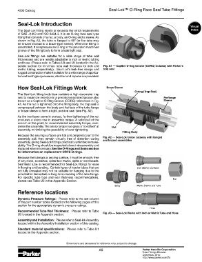
How Seal-Lok Fittings Work Braze Sleeve
O-ring (Trap-Seal)
The Seal-Lok fitting body face contains a high durometer trap
seal to maximize retention in a precision machined groove also Parflange
known as a Captive O-Ring Groove (CORG) referenced in Fig. Sleeve
A1. As the nut is tightened onto the fitting body, the trap seal is
compressed between the body and flat face of the tube flange
or braze sleeve to form a tight, positive seal (see Fig. A2).
As the two faces come in contact, further tightening of the nut
produces a sharp rise in assembly torque. A solid pull of the
wrench at this point, to recommended assembly torque, com-
pletes the assembly. The sharp torque rise gives a “solid feel” at Nut
assembly, minimizing the possibility of over tightening.
Fitting Body
Because the sealing surfaces are flat and perpendicular to the
assembly pull, they remain virtually free of distortion during Fig. A2 — Seal-Lok Union cutaway with flanged
and brazed assemblies
assembly, giving Seal-Lok fittings practically unlimited remake-
ability. The O-ring should be inspected at each disassembly and
replaced when necessary. See the O-Rings and Seals section
for information on replacement ORFS O-rings.
Because the tubing is a sealing surface, it must be smooth, free
of any nicks, scratches, spiral tool marks, splits or weld beads.
Seamless tube is recommended for Seal-Lok fittings for ease
in flanging and bending. Certain types of harder tubes that are Inch Sleeve and Tube
not fully annealed may not be suitable for flanging due to the
potential for immediate or long-term cracking of the tube flange.
For specific tube type and wall thickness recommendations, Nut
please see Table U3 in the Appendix Section.
Body Metric Sleeve and Tube
Reference locations
Dynamic Pressure Ratings: Please refer to the last column
of the part number tables located on the following pages of this
section for the appropriate dynamic pressure ratings.
Hose
Recommended Tube Wall Thickness: Please refer to Table
U3 located in the Appendix section. Fig. A3 — Seal-Lok Works with Inch or Metric Tube and Hose
Assembly and Installation: Please refer to Seal-lok Assembly
located within the Assembly/Installation section of this catalog.
Standard material specifications: Please refer to Table U1
located in the Appendix section.
Dimensions and pressures for reference only, subject to change.
A5 Parker Hannifin Corporation
Tube Fittings Division
Columbus, Ohio
http://www.parker.com/tfd