
Page 2 - Parker - Fulflo M series single cartridge vessels
P. 2
®
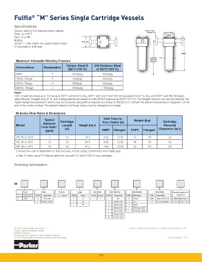
Fulfl o “M” Series Single Cartridge Vessels
Specifi cations
Carbon steel or 316 stainless steel material
Drain: ¼ in NPT
Vent: ¼ in NPT
Bolting:
(4) 5/8-11 UNC bright zinc plated carbon steel
O-ring head to shell seal
Maximum Allowable Working Pressure
Carbon Steel @ 316 Stainless Steel
Connections Designation
250°F (121°C) @ 250°F (121°C)
FNPT T 1610psig 1610psig
150 lb. Flange F 245psig 225psig
300 lb. Flange H 665psig 590psig
600 lb. Flange J 1332psig 1180psig
Note:
FNPT maximum pressure is 1610psig at 300°F with EPR O-ring, 400°F with Viton* and FEP encapsulated Viton* O-ring, and 500°F with FEP Encapsu-
lated Silicone. Flanged units (F, H, and J designations) are based on ANSI B16.5 pressure at 250°F (121°C). The fl anged versions can also be rated for the
higher design temperature in which case the pressure rating will be reduced according to ANSI B16.5. Indicate the desired temperature in degrees F at the
end of the model number. The gasket material and fl ange rating must be changed accordingly.
M Series Flow Rates & Dimensions
Inlet Face-to-
Typical Weight (lbs)
Cartridge Face Outlet (in) Cartridge
Aqueous
Model Length Height (in) ‡ Removal
Flow Rate† (in) Clearance (in) ‡
(gpm) FNPT Flanged FNPT Flanged
MC (N or U)1S 6 10 14.5 4.62 12.62 37 45 22
MC (N or U)1D 12 20 24.5 4.62 12.62 46 54 42
MC (N or U)1T 18 30 34.5 4.62 12.62 55 63 62
† Actual fl ow rate is dependent on fl uid viscosity, micron rating, contaminant and media type.
‡ Add 3” when using TC internal option for use with TC style 2-222 O-ring cartridges.
Ordering Information
M
Material Design Columns Length Inlet | Outlet Inlet | Outlet Type Gasket Material Internal Option Special Temperature for
Flanged Units
C Carbon Steel CODE Description 1 1 Element CODE Inches CODE Inches CODE Description CODE Description CODE Description
S 316SS N Non-Code S 10" 1 1" T FNPT N Buna-N Blank Center Post for DOE CODE Description
U ASME U-Stamp D 20" F Flanged 150# E EPR TC 222 O-ring Adapter Blank 250º (121°C)
T 30" H Flanged 300# V Viton ®
J Flanged 600# T FEP Encap. Viton ®
K Flanged 900# L FEP Encap. Silicone
L Flanged 1500#
M Flanged 2500#
© 2010 Parker-Hannifi n Corporation Viton is a registered trademark of E.I. DuPont de Nemours & Co., Inc.
Process Advanced Filtration Division
All Rights Reserved
Specifi cations are subject to change without notifi cation
For User Responsibility Statement, see www.parker.com/safety SPEC- M Vessel 1/10
118