
Page 170 - Parker - Parker Pneumatic
P. 170
PDE2600PNUK
Parker Pneumatic Origa OSP-L Rodless Cylinders
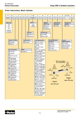
Order Instructions- Basic Cylinder
1-4 5+6 7 8 9 10 11 12-16 17 18 19 20 21 22 23 24 25
OSPL 25 0 0 0 0 0 01100 0 0 0 0 0 0 0 0 0
Piston-Ø Stroke Piston add. Guide Measuring
Mounting Carriage system
25 in mm
(5 digits) 0 without 0 without 0 without
32
40 1 clevis
mounting
in progress
in progress
Screws Cushioning
0 standard 0 standard
1 Stainless 1 max. length
Version / Piston Lubrication End cap position Guides/ Brakes/ Cover /
Inversion Cable Channel
0 standard 0 standard 0 l+r 0° = in front
0 without 0 standard
1 Tandem 1 l+r 90° = under-
neath Inversion 1 Cable channel
M
2 l+r 180° = at the Ø 16-80 2 Cable channel
back Duplex two-sided
Air Connection Seals 3 l+r 270° = same side N Ø 25,32,40,50
0 standard 0 standard as outerband
1 end face 4 l 90° = underneath;
r 0° = in front
2
both at one end 5 l 180° = at the back;
r 0° = in front
3 left standard
right end face 6 l 270° = same side
as outerband;
4 right standard r 0° = in front End cap position
left end face (air connection) 270°
7 l 0° = in front; same
A 3/2 Way valve r 90° = underneath 270° side as
VOE 24 V = same 180° outerband
Ø 25,32,40,50 8 l 180° = at the back; at the back
r 90° = underneath side as end-face
B 3/2 Way valve 180° outerband
VOE 230 V~ / 110 V= 9 l 270° = same side at the back
Ø 25,32,40,50 as outerband; 0°
r 90° = underneath
C 3/2 Way valve in front
VOE 48 V = A l 0° = in front; end-face 0° 90°
Ø 25,32,40,50 r 180° = at the back in front underneath
B l 90° = underneath;
E 3/2 Way valve 90° Cylinder
VOE 110 V~ r 180° = at the back underneath R
Ø 25,32,40,50 C l 270° = same side (right end side)
as outerband; Cylinder
r 180° = at the back L
D l 0° = in front; (left end side)
r 270° = same side
as outerband
E l 90° = underneath;
r 270° = same side
as outerband
F l 180° = at the back;
r 270° = same side
as outerband
Parker Hannifin Corporation
Origa Division - Europe
170