
Page 588 - Parker - Parker Pneumatic
P. 588
PDE2600PNUK
Parker Pneumatic 3/2, 5/2 and 5/3 Directional Control Valves - Series S9
3/2, 5/2 and 5/3 Way Valves for use in EX areas
Series S9-G1/8 / G1/4 / G1/2
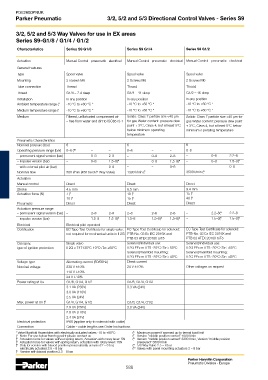
Characteristics Series S9 G1/8 Series S9 G1/4 Series S9 G1/2
Actuation Manual Control pneumatic electrical Manual Control pneumatic electrical Manual Control pneumatic electrical
General Features
Type Spool valve Spool valve Spool valve
Mounting 2 screws M5 2 Screws M6 2 Screws M6
Tube connection Thread Thread Thread
Thread G1/8 – 7.4 deep G1/4 – 11 deep G1/2 – 16 deep
Installation In any position In any position In any position
Ambient temperature range ( 1 -10 °C to +60 °C * -10 °C to +60 °C * -10 °C to +60 °C *
Medium temperature range ( 1 -10 °C to +60 °C * -10 °C to +60 °C * -10 °C to +60 °C *
Medium Filtered, unlibricated compressed air Solids: Class 7 particle size <40 µm Solids: Class 7 particle size <40 µm for
– free from water and dirt to ISO8573-1 for gas Water content: pressure dew gas Water content: pressure dew point
point + 3°C, Class 4, but at least 5°C + 3°C, Class 4, but at least 5°C below
below minimum operating minimum o perating temperature
temperature
Pneumatic Characteristics
Nominal pressure (bar) 6 6 6
Operating pressure range (bar) 0–8 ( 10 – – 0–8 – – 0–8 – –
– permanent signal version (bar) – 0–8 2–8 – 0–8 2–8 – 0–8 2.2–8
– impulse version (bar) – 0–8 1.5–8( 4 – 0–8 1.5–8( 4 – 0–8 1.5–8( 4
– with external pilot air (bar) – – 0–8 – – 0–8 – – 0–8
Nominal flow 500 l/min (450 bei 3/2 Way Valve) 1300 l/min ( 7 3500 l/min ( 8
Actuation
Manual control Direct Direct Direct
Stroke 4.5 mm 6.5 mm 9.4 mm
Actuation force (N) 7 ( 2 10 ( 2 15 ( 2
10 ( 3 15 ( 3 40 ( 3
Pneumatic Direct Direct Direct
Actuation pressure range
– permanent signal version (bar) – 2–8 2–8 2–8 2–8 2–8 – 2.2–8( 9 2.2–8
– impulse version (bar) – 1.5–8 1.5–8( 4 1.5–8 1.5–8( 4 1.5–8( 4 – 1.5–8( 5 1.5–8( 4
Electrical Electrical pilot operated
Certification EC Type Test Certificate for single valve: EC Type Test Certificate for solenoid: EC Type Test Certificate for solenoid:
not required for mechanical units in II 2G PTB-No. 03 Ex IEC 2019X and PTB-No. 03 Ex IEC 2019X and
PTB 03 ATEX 2018X toT5 PTB 03 ATEX 2018X toT5
Category, Single valve Solenoid/individual use: Solenoid/individual use:
type of ignition protection II 2G c T4T135°C-10°C≤Ta≤+60°C II 2G EEx m II T5 -20°C≤Ta≤+50°C II 2G EEx m II T5 -20°C≤Ta≤+50°C
Solenoid/manifold mounting: Solenoid/manifold mounting:
II 2G EEx m II T5 -20°C≤Ta≤+40°C II 2G EEx m II T5 -20°C≤Ta≤+40°C
Voltage type Alternating current (50/60Hz) Direct current
Nominal voltage 230 V ± 10% 24 V ± 10% Other voltages on request
110 V ± 10%
24 V ± 10%
Power rating at Un G1/8, G1/4, G1/2 G1/8, G1/4, G1/2
3.1 VA (230V) 3.3 VA (24V)
3.0 VA (110V)
2.5 VA (24V)
Max. power at Un ( 6 G1/8, G1/4, G1/2 G1/8, G1/4, G1/2
2.9 VA (230V) 3.0 VA (24V)
2.8 VA (110V)
2.4 VA (24V)
Electrical protection IP65 (applise only to solenoid with cable)
Connection Cable – cable lengths see Order Instructions
6
* Valve Manifold Assemblies with electrically actuated valves -10 to +50°C ( Maximum power if warmed up to termal load limit
( 1 Note: For use below freezing point please contact us ( Version “middle position vented“ 1000 l/min
7
( 2 Actuation force for valves without spring return, Actuation with rotary lever: 5N ( Version “middle position vented“ 3300 l/min, Version “middle position
8
( 3 Actuation force for valves with spring return, actuation with rotary lever: 15N pressured“ 3600 l/min
( 4 Only for version with biased position pneumatically actuated 2 – 8 bar, ( 5/3 Way Valve 2.5 – 8 bar
9
electrically actuated 2.5 – 8 bar ( 10 Valves with panel mounting actuators 2 – 8 bar
( Version with biased position 2.5 – 8 bar
5
Parker Hannifin Corporation
Pneumatic Division - Europe
588