
Page 718 - Parker - Parker Pneumatic
P. 718
PDE2600PNUK
Parker Pneumatic Pressure Switches
Pressure Switches Electronic
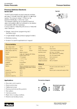
Series EDP Symbol
The EDP electronically actuated pressure switches P 1 +Uc
2 SP2
are used to convert pneumatic signals into electrical I 3 GND
signals. The pressure range 0-16 bar can be 4 SP1
adjusted individually, in either bar or psi.
The pressure switches can be used as threshold
value comparators with one hysteresis or as window
comparators with two hystereses.
A robust ceramic measuring cell acts as a measured
value transducer.
• Simple, menu-driven programming via 3
membrane keys
• 3-digit red LED display (pressure gauge function)
• Electronic locking
• Versions for specific applications on request
Characteristics
Type - flange version EDP-V EDP Voltage 18 - 32 V
Setting range Pmin/max (bar) -1 to 0 0-16 Voltage type Direct current
Safety pressure relief Pmax 100 bar 100 bar Power consumption < 80 mA without switching outlet
Port size Flange connection Switching current SP1 max. 1.3 A (PIN4)
SP2 / ERROR max. 0.3A (PIN2)
Display 3 digit, red 7-Segment LED-Display,
programmable 0 /180 O Switching logic NO / NC programmable
O
Display for operating status LED red/green Switching outlet Short circuit proof
Linearity % <± 0.2 to 1.5 p N Electrical connection Plug M12x1
TK zero point % <± 0.2 p N Degree of protection IP67 to EN 60529
Installation In any position
Weight (mass) 0.100 kg Material
Medium Filtered compressed air, lubricated or Housing PA, part in contact with medium: AI
unlubricated, weakly acidic or weakly
alkaline fluids Measuring cell Ceramic
O
Ambient Tmin -20 C Seals Buna N, part in contact with medium: FKM
O
temperature range Tmax +70 C
O
Medium Tmin -20 C
O
temperature range Tmax +70 C
Applications Connection diagram
• Pneumatic control systems 5
• Pressing technology Electrical connection
• Welding technology 4 3 1 = bn (brown) +Uc
2 = ws (white)
SP2
• Packing machines and filling systems 1 2 3 = bl (blue) GND
• Test systems 4 = sw (black) SP1
• Clamping systems
• Plastic blow-moulding machinery
• Robotics and handling industry
Parker Hannifin Corporation
Pneumatic Division - Europe
718