
Page 7 - Apollo - Butterfly Valves: Resilient Seated & Doubled Offset High Performance
P. 7
BUTTERFLY VALVES – Resilient Seated
Installation
Apollo® butterfly valves are designed for installation between ANSI Class 125/150 lb. weld-neck or slip-on flanges. While we
suggest use of weld neck flanges, Apollo® models are configured to also accept slip-on flanges that eliminate failures associated
with conventional butterfly valves. Be sure to properly align flange and valve when using raised face flanges. Type C stub end
flanges are not recommended.
Apollo butterfly valves can be used with schedule 40 and schedule 80 steel pipe. When the valve is properly centered between
flanges, the disc of an open butterfly valve will not contact the inside diameter of schedule 40 or schedule 80 steel pipe.
Caution: Adjacent piping and components with reduced inside diameters (Lined pipe, Schedule 80 plastic pipe, As-cast rough fittings,
etc) could cause disc-pipe contact which could damage the valve’s disc and shaft.
INSTALLING WD/LD SERIES VALVES MAINTENANCE
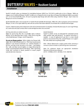
Begin by positioning the disc at partially open; maintain Apollo® butterfly valves are designed for extended service
the disc within the body face-to-face. After positioning the with minimal wear and servicing. No regular lubrication is
valve body between flanges, install flange bolts. needed. In case of replacement, put disc in a near closed
position and remove from line, spread flanges and support
Do not use flange gaskets. Before tightening flange bolts, the valve while removing flange bolts.
adjust disc to the full open position. This helps assure proper
alignment and clearance between the outside diameter of Note: Always depressurize a piping system when removing a
the disc and the inside diameter of the pipe. Hand tighten manual or power actuator or performing valve maintenance.
the bolts and then wrench tighten in stages following the
proper sequential bolt order for the flange. After tightening, Note: For additional details see appropriate Installation
rotate disc carefully to closed position to assure proper Operation & Maintenance Manual.
outside diameter clearance. (LD141 - I979900, LD145 - I981800, LC149 - I980700)
Closed Partially Open Open
For additional information, submittal sheets and manuals, visit www.apollovalves.com
7
Customer Service (704) 841-6000