Page 77 - Apollo - Commercial Products Catalog
P. 77

SAFETY VALVES

                                                                        ASME sections I & VIII


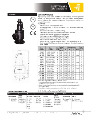
             119 SERIES                              CAST IRON SAFETY VALVE
                                                     High capacity safety valves ideal for use with all types of boilers, pressure
                                                     vessels and pressure piping systems.   Their top-guided design includes
                                                     two control rings that ensure seat tightness.  Direct replacement for most
                                                     competitive models.
                                              UV
                                                    A S FEATURES
                                                      M
                                                       E
                                                     •   Set pressures to 250 psig @ 450°F max
                                                     •   Flanged inlet sizes:  1-1/2” through 6” ANSI 250 lb; some sizes available in
                                                        female NPT
                                              V
                                                    A S •  National Board Certified ASME flow ratings
                                                      M
                                                       E
                                                     •  316 stainless steel wetted trim (disc and nozzle) is standard
                                                     •  Metal to metal seating, lapped to optical flatness
                                                     •  Semi-nozzle design available in eight orifice sizes
                                                     •  Rust proof steel stem, spring and spring washers
                                                     •  Drip pan elbows are available (see page 82)
                                                     •  Registered in all Canadian Provinces Under CSA B51, CRN #0G8547.5C
                                                     •  Optional dual ASME/European Pressure Equipment Directive Compliance
                                                     •  Made in USA
                                                         Series      Valve     Orifice  Orifice   Dimensions (in.)  Wt./
                                                                                    Area
                                                        Number      Size (in.)  Letter  (sq. in.)  A  B  C  Hex D  (lbs.)
                                                                                                                 APP
                                                        119 JGC  1-1/2 250# x 2 1/2 FNPT  J  1.36  15.00  4.00  4.31     35
                                                        119 KHC   2 250# x 3 FNPT  K  1.93  16.00  4.00  4.62    36
                                                        119 KHA   2 FNPT x 3 FNPT  K  1.93  16.00  4.00  4.62  3-3/4  37
                                                        119 KJC  2-1/2 250# x 3 FNPT  K  1.93  16.00  4.00  4.62  41
                                                        119 KKC   3 250# X 3 FNPT  K  1.93  16.00  4.00  4.63    45
                                                        119 LJC  2-1/2 250# x 4 FNPT  L  2.99  22.00  5.12  5.62  84
                                                        119 LJA  2-1/2 FNPT x 4 FNPT  L  2.99  22.00  5.12  5.62  5-3/8  81
                                                        119 LKC   3 250# x 4 FNPT  L  2.99  22.00  5.12  5.62    85
                                                        119 LMC   4 250# X 4 FNPT  L  2.99  22.00  5.13  5.63    90
                                                        119 MKA   3 FNPT x 4 FNPT   M  3.77  22.00  5.12  5.62  5-3/8  80
                                                        119 MKC   3 250# x 4 FNPT  M  3.77  22.00  5.12  5.62    87
                                                        119 MMC   4 250# X 4 FNPT  M  3.77  22.00  5.13  5.63    95
                                                        119 NMD   4 250# x 6 125#  N  4.55  28.00  7.25  6.75    210
                                                        119 PMD   4 250# x 6 125#  P  6.69  28.00  7.25  6.75    215
                                                        119 QPD   6 250# x 8 125#  Q  11.59  42.00  10.00  9.25  530
                                                        119 RPD   6 250# x 8 125#  R  16.79  42.00  10.00  9.25  530
                                                     Information required for ordering 119 series valves:
                                                     1.   Determine the orifice letter that corresponds to your required flow rate from
                                                        the following capacity charts.
                                                     2.   Select the inlet x outlet connection options from the list of models available for
                                                        that orifice (above).
                                                     3.   Specify base model number, set pressure, ASME Code section and service.

           119 SERIES NUMBERING SYSTEM               For Further information request catalog SRCA9000
            119            K          H         C            A              MAA         0150         Q
            SERIES NUMBER  ORIFICE    INLET (IN.) CONNECTION  SERVICE       SPECIAL     SET PRESSURE  SUFFIX
                           LETTER
                                                                            OPTIONS
            119 = Stainless Steel The orifice letter  G = 1-1/2  A = FNPT x FNPT  A = Sec I Steam  Factory issued   Set Pressure, PSIG Q = Performance
                          Wetted Trim  from the Capacity H = 2  C = 250# x FNPT  K = Sec VIII Air  letters/numbers     (4 digits)  (Calibration) test reports
                           Chart (pg. 84)  J =  2-1/2  D = 250# x 125#  L = Sec VIII Steam  (MAA default)
                                      K = 3                  N = Non Code Air  MCE = CE/PED
                                      M = 4                  P = Non Code Steam
                                      P = 6

                                                                                                                    77
           See Safety & Relief Valve Catalog (SRCA9000) for more detailed information about the products in this section.
   72   73   74   75   76   77   78   79   80   81   82