Page 5 - Proportion-Air - BB1 & BB2
P. 5

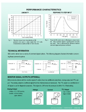
PERFORMANCE CHARACTERISTICS

                                LINEARITY                                    RESPONSE TO STEP INPUT
                                  LINEARITY                                   RESPONSE TO STEP INPUT
                                                                      100
                100
                                                                      90                              Command
                 90                                                   80                              Pressure
               Pressure [% of scale]  70                            % of Scale  60
                 80
                                                                      70
                 60
                                                                      50
                 50
                                                                      40
                 40
                                                                      30
                 30
                                                                      20
                 20
                                                                      10
                 10
                                                                       0
                  0
                                                                        -100  0  100  200  300  400  500  600  700
                    0   1   2  3   4   5   6   7   8   9  10                             Time [ms]
                                 Command [Volts]                                                     Volume=2 cu. in.
             Fig. 1   This chart shows linear characteristics of BB   Fig. 2   Times for BB control valve to fill/exhaust a closed cham-
                    products  when  given  a  ramp  signal  from  0-10  volts.    ber.    Step  command  signal  is  superimposed  over  pres-
                    Characteristics would be similar for 4-20 mA units.   sure  trace.    Time  is  determined  by  difference  between
                                                                         command signal and pressure achieved.


            TECHNICAL INFORMATION

            BB2 control valves have a variety of command signal options.  The following diagrams illustrate information concern-

            ing these command options.


            MONITOR SIGNAL OUTPUTS (OPTIONAL)

            BB2 products ordered with the monitor signal (F option) have two additional output lines, analog output and TTL out-

            put.  The analog output is a buffered signal from the internal pressure transducer.  The TTL signal is a conditional on/
            off signal to use for diagnostic purposes.  This signal is LOW when the pressure is within 1% of final setting.

            Analog Output                       Voltage              Current             TTL Output
                 Voltage = 0-10  VDC sourcing                                                 Low = 0 VDC
                                                             -                        +                             -
                 Current = 4-20 mA sinking            PIN 3                   PIN 5           High = 5 VDC   PIN 3
                                                           V                        mA
                                 (open collector)
                                                       PIN 2                    PIN 2                         PIN 4
                                                             +                                                      +
                                                                                      -


                                                                          LET’S TALK 317-335-2602   *   PROPORTION-AIR   *   BRBB021506E   5
   1   2   3   4   5   6   7   8