
Page 58 - Parker- Parker global air preparation system
P. 58
Catalog 0750-3 US P31P & P32P Series
Global Air Preparation System Proportional Regulators
Technical information Advanced functionality
Dead band Pilot valve protection
The dead band is preset at 1.3% of Full Scale*, adjustable via When the required output pressure can not be achieved
parameter 13. because of a lack of input pressure the unit will open fully and
Accuracy will display NoP. Approximately every 10 seconds the unit will
Linearity: = < 0.3% of Full Scale.* retry. The output pressure will then be approximately equal to
Proportional band the inlet pressure. As soon as the input pressure is back on the
required level, the normal control function follows.
The proportional band is preset at 10% of Full Scale.*
Fail safe operation Safety exhaust
Should the control signal fall below 0.1 volts the valve will
• If the P31P / P32P unit has an “0” or “A” in the 12th digit of automatically dump downstream system pressure .
the model number
– When the supply voltage drops, the electronic control Input protection
reverts to the fail safe mode. The last known output The unit has built-in protection against failure and burnout
pressure is maintained at approximately the same level resulting from incorrect input value, typically:
depending upon air consumption. The digital display The 24VDC supply is incorrectly connected to the setpoint
indicates the last known pressure setting. input, the display will show ‘OL’, as an overload indication. The
– When the supply voltage is reinstated to the correct unit will need to be rewired and when correctly connected will
level, the valve moves from the fail safe mode and the operate normally.
output pressure immediately follows the control signal The overload indicator ‘OL’ will also appear should the
requirement. The display indicates the actual output wrong input value be applied or the wrong input value
pressure. be programmed: 4 - 20m instead of 0 - 10V. To correct
– Note: In the event of loss of both power and inlet this a different set point value should be input or the unit
pressure the unit will exhaust downstream pressure. reprogrammed to correct the set point value acceptance. (via
• If the P31P / P32P unit has an “E” in the 12th digit of the parameter 4).
model number
– When the supply voltage drops, the electronic control Response time P31P P32P
reverts to “Forced Exhaust Mode” and will automatically 2 to 4 bar 25 msecs 35 msecs
exhaust the downstream (regulated) pressure. 1 to 6 bar 55 msecs 135 msecs
– When the supply voltage is reinstated to the correct level 4 to 2 bar 70 msecs 85 msecs
the unit will return to normal operation and follows the 6 to 1 bar 80 msecs 225 msecs
control signal requirement. The display indicates the To fill volume of:
actual pressure. 100cm - P31P
3
3
• If the unit has been programmed in manual mode (not with 330cm - P32P
a control signal) the unit will EXHAUST and the regulator will connected to the outlet of the regulator.
need to be reset when power is applied. Settings
Full exhaust The regulator is pre-set at the factory. If required, adjustments
Complete exhaust of the regulator is defined as can be made.
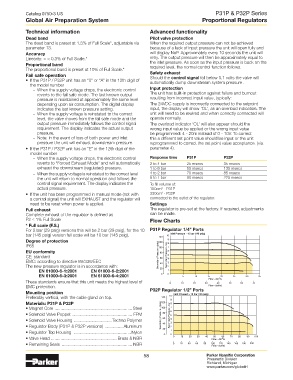
P2 ≤ 1% Full Scale Flow Charts
* Full scale (F.S.)
For 2 bar (29 psig) versions this will be 2 bar (29 psig), for the 10 P31P Regulator 1/4” Ports
bar (145 psig) version full scale will be 10 bar (145 psig). 140 10 Inlet Pressure - 10 bar (145 psig)
Degree of protection 120 9 8
IP65 100 7
EU conformity 80 6
CE: standard Secondary Pressure - (psig) 60 Secondary Pressure - bar 5 4
EMC: according to directive 89/336/EEC 40 3
The new pressure regulator is in accordance with: 2
EN 61000-6-1:2001 EN 61000-6-2:2001 20 1
EN 61000-6-3:2001 EN 61000-6-4:2001 0 0 5 10 15 20 25 30 35
3
Flow - dm /s
These standards ensure that this unit meets the highest level of 0 10 20 30 40 50 60 70
EMC protection. Flow - (scfm)
Mounting position P32P Regulator 1/2” Ports
Inlet Pressure - 10 bar (145 psig)
Preferably vertical, with the cable gland on top. 140 10
9
Materials: P31P & P32P 120 8
• Magnet Core .................................................................Steel 100 7
• Solenoid Valve Poppet .................................................. FPM Secondary Pressure - (psig) 80 Secondary Pressure - bar 6 5
• Solenoid Valve Housing ................................Techno Polymer 60 4 3
• Regulator Body (P31P & P32P versions) ............... Aluminum 40 2
20
• Regulator Top Housing ................................................Nylon 0 1 0
50
60
• Valve Head ....................................................... Brass & NBR 0 10 20 30 40 Flow - dm /s 70 80 90 100
3
• Remaining Seals ........................................................... NBR 0 20 40 60 80 100 120 140 160 180 200
Flow - (scfm)
58 Parker Hannifin Corporation
Pneumatic Division
Richland, Michigan
www.parker.com/globalfrl