
Page 15 - Parker - PGP/PGM300 Series (Cast Iron Brusing Design)
P. 15
Catalog HY09-0300/US PGP/PGM300 Series
PGP/PGM300 Series - Dimensional Data Cast Iron Bushing Design
Dimensional Data
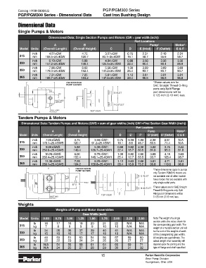
Single Pumps & Motors
Dimensional Data: Single Section Pumps and Motors (GW = gear width (inch))
Port Locations
A B Pump 1 Motor 1
Model Units (Overall Length) (Overall Height) C D E (Inlet) F (Outlet) E & F
inch 4.27+GW 4.75 3.27+GW 0.75 2.31 2.19 2.31
315 mm 108.5+25.4GW 120.7 83.1+25.4GW 19.1 58.7 55.6 58.7
inch 6.19+GW 5.88 4.94+GW 0.88 3.56 3.56 3.50
330 mm 157.2+25.4GW 149.4 125.5+25.4GW 22.4 90.4 90.4 88.9
inch 7.06+GW 6.00 5.56+GW 1.00 3.69 3.69 3.69
350 mm 179.3+25.4GW 152.4 141.2+25.4GW 25.4 93.7 93.7 93.7
inch 7.31+GW 7.25 5.81+GW 1.12 3.81 3.81 3.81
365 mm 185.7+25.4GW 184.2 147.6+25.4GW 28.4 96.8 96.8 96.8
A CW ROTATION 1 These values are for
PUMP SHOWN SAE Straight Thread O-Ring
ports only.Split Flange
E INLET port dimensions will be
D
0.125 inch (3.18 mm) less.
B
INLET AND
OUTLET
F OUTLET
INLET AND TOP VIEW
C OUTLET
Tandem Pumps & Motors
Dimensional Data: Tandem Pumps and Motors (GWS = sum of gear widths (inch) GW1=First Section Gear Width (inch))
Port Locations
A B Pump Motor 2
2
2
Model Units (Overall Length) (Overall Height) C D E 1 F 1 G (Inlet) H (Outlet) G & H
inch 7.05+GWS 4.75 3.59+GW1 0.75 0.34 1.84 2.38 2.81 N/A
315 mm 179.1+25.4GWS 120.7 91.2+25.4GW1 19.1 8.6 46.7 60.5 71.4 N/A
inch 9.88+GWS 5.88 5.38+GW1 0.88 0.62 2.38 3.22 3.75 3.22
330 mm 250.9+25.4GWS 149.4 136.7+25.4GW1 22.4 15.7 60.5 81.8 95.3 81.8
inch 10.25+GWS 6.00 5.75+GW1 1.00 0.50 2.50 3.69 4.15 3.69
350 mm 260.4+25.4GWS 152.4 146.1+25.4GW1 25.4 12.7 63.5 93.7 105.4 93.7
inch 11.38+GWS 7.25 6.25+GW1 1.12 0.63 2.88 3.81 4.71 3.81
365 mm 289.1+25.4GWS 184.2 158.8+25.4GW1 28.4 15.9 73.2 96.8 119.6 96.8
A CW ROTATION 1
PUMP SHOWN These dimensions apply to pumps
only. Tandem PGM315 motors are
E G INLET not available and all other models
have motors that are available with
INLET only single outlet ports.
D F B
2 These values are for SAE Straight
H OUTLET
Thread O-Ring ports only. Split
Flange port dimensions will be
TOP VIEW
INLET AND 0.125 inch (3.18 mm) less.
C OUTLET
Weights
Weights of Pump and Motor Assemblies
Gear Width (inch)
Model Units 0.50 0.75 1.00 1.25 1.50 1.75 2.00 2.25 2.50 Note: The weight of a single
section unit is the value shown for
lb 16 17 18 19 20 21 22 N/A N/A
315 kg 7 8 8 9 9 10 10 N/A N/A the corresponding gear width. The
weight of a multiple section unit will
lb 34 35 36 37 39 40 41 N/A N/A be the sum of the weights of each
330 kg 15 16 16 17 17 18 19 N/A N/A of the corresponding gear widths.
lb 48 50 51 53 54 56 57 59 60 All weights are approximate. The
350 kg 22 22 23 24 24 25 26 27 27 actual weight of an assembly will
lb N/A 54 56 59 61 64 66 69 71 depend upon the porting and the
365 kg N/A 24 25 27 28 29 30 31 32 type of flange and shaft specified.
15 Parker Hannifin Corporation
Gear Pump Division
Youngstown, Ohio USA