
Page 1 - Exlar - High temperature hazardous location control
P. 1
EXP-24 Positioner
High Temperature
Hazardous Location 0081
Control II 2 G
LCIE 09 ATEX 3057 X
Ex d II B T5
Exlar’s EXP-24 Positioner has been IP66
designed for use specifi cally with
Exlar’s EL100 Actuator and also can 163694
Class I Division 1
be used to drive most three phase Group B, C, D, T5
linear actuators and rotary motors.
The EXP-24 positioner off ers a fully
capable 24VDC motion controller
and brushless servo motor amplifi er
that conforms to CSA and the EU
ATEX Directive 94/9/EC for explo-
sion-proof applications.
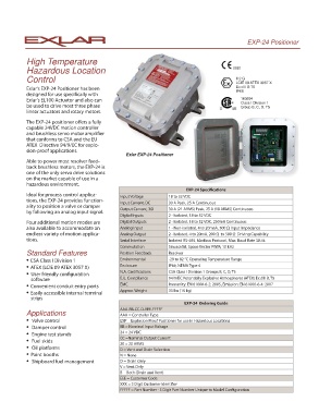
Exlar EXP-24 Positioner
Able to power most resolver feed-
back brushless motors, the EXP-24 is
one of the only servo drive solutions
on the market capable of use in a
hazardous environment.
EXP-24 Specifi cations
Ideal for process control applica- Input Voltage 18 to 32 VDC
tions, the EXP-24 provides function-
Input Current, DC 30 A Peak, 25 A Continuous
ality to position a valve or damper
Output Current, 3Ø 30 A (21 ARMS) Peak, 25 A (18 ARMS) Continuous
by following an analog input signal.
Digital Inputs 2 - Isolated, 18 to 32 VDC
Four additional motion modes are Digital Outputs 2 - Isolated, 18 to 32 VDC, 250mA Continuous
also available to accommodate an Analog Input 1 - Non-isolated, 4 to 20maA, 500 Ω Input Impedance
endless variety of motion applica- Analog Output 2 - Isolated, 4 to 20mA, 200 Ω to 500 Ω Driving Capability
tions. Serial Interface Isolated RS-485, Modbus Protocol, Max. Baud Rate 38.4k
Commutation Sinusoidal, Space Vector PWM, 10 kHz
Standard Features Position Feedback Resolver
• CSA Class I Division 1 Environmental -29 to 82 °C Operating Temperature Range
Enclosure IP66, NEMA Type 4
• ATEX (LCIE 09 ATEX 3057 X)
N.A. Certifi cations CSA Class I Division 1 Groups B, C, D, T5
• User friendly confi guration
software E.U. Compliance 94/9/EC Potentially Explosive Atmospheres (ATEX) Ex d II B, T5
EMC Immunity: EN 61000-6-2: 2005, Emission: EN 61000-6-4: 2007
• Convenient conduit entry ports
Approx. Weight 33 lbs (15 kg)
• Easily accessible internal terminal
strips
EXP-24 Ordering Guide
AAA-BB-CC-D-EEE-FFFFF
Applications AAA = Controller Type
• Valve control EXP = Explosion Proof Positioner for use in Hazardous Locations
• Damper control BB = Nominal Input Voltage
24 = 24 VDC
• Engine test stands
CC =Nominal Output Current
• Fuel skids
20 = 20 ARMS
• Oil platforms D = Vent and Drain Selection
• Paint booths N = None
• Shipboard fuel management D = Drain Only
V = Vent Only
B = Both (Drain and Vent)
EEE = Customer Code
XXX = 3 Digit Customer Identifi er
FFFFF = Part Number - 5 Digit Part Number Unique to Model Confi guration