Page 45 - Paker - Medium Duty Hydraulic Cylinders
P. 45

Catalog HY08-1130-4/NA                            Medium Duty Hydraulic Cylinders
            Mounting Information – 6.00" & 8.00" Bore         Series 3L


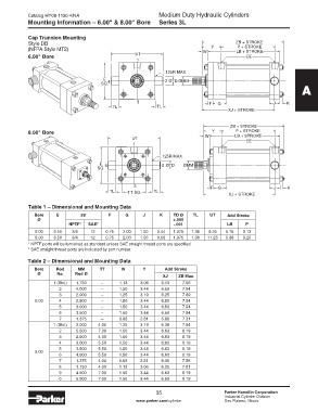
            Cap Trunnion Mounting
            Style DB                                                                        ZB + STROKE
                                                                                            P + STROKE
            (NFPA Style MT2)                                                   W  Y         LB + STROKE
            6.00" Bore                               UT                                         EE
                                                      1

                                                                .125R MAX.
                                         E                       2 ØTD ØMM
                                        SQ. 4
                                                                                                                     A

                                                      3                           F  G                    J    K
                                            TL               TL
                                                                                         XJ + STROKE


                                                                                          ZB + STROKE
            8.00" Bore                                                             Y        P + STROKE
                                                    UT                          W          LB + STROKE
                                                                                                EE
                                                    1
                                                               .125R MAX.
                                       E  4                    2 ØTD    ØMM
                                       SQ.


                                                     3                            F  G                    J     K
                                           TL     TT SQ.    TL
                                                                                         XJ + STROKE

            Table 1 – Dimensional and Mounting Data
              Bore     E        EE         F     G      J      K    TD Ø   TL     UT     Add Stroke
               Ø                                                    +.000
                            NPTF 1   SAE 2                          -.001               LB      P
               6.00   6.50   3/4    12    0.75  2.00   1.50   0.44  1.375  1.38  9.25   5.75   3.13
               8.00   8.50   3/4    12    0.75  2.00   1.50   0.56  1.375  1.38  11.25  5.88   3.25
            1  NPTF ports will be furnished as standard unless SAE straight thread ports are specified.
            2  SAE straight thread ports are indicated by port number.

            Table 2 – Dimensional and Mounting Data
              Bore            Rod   MM   TT     W       Y       Add Stroke
               Ø       No.    Rod Ø
                                                                XJ    ZB Max.
                      1 (Std.)  1.750   –      1.13    3.06    6.13    7.56
                        2     4.000     –      1.50    3.44    6.50    7.94
                        3     2.000     –      1.25    3.19    6.25    7.69
               6.00     4     2.500     –      1.50    3.44    6.50    7.94
                        5     3.000     –      1.50    3.44    6.50    7.94
                        6     3.500     –      1.50    3.44    6.50    7.94
                        7     1.375     –      0.88    2.81    5.88    7.31
                      1 (Std.)  2.000  4.00    1.25    3.19    6.38    7.94
                        2     5.500    7.00    1.50    3.44    6.63    8.19
                        3     2.500    4.00    1.50    3.44    6.63    8.19
                        4     3.000    5.50    1.50    3.44    6.63    8.19
                        5     3.500    5.50    1.50    3.44    6.63    8.19
               8.00
                        6     4.000    5.50    1.50    3.44    6.63    8.19
                        7     1.375    4.00    0.88    2.81    6.00    7.56
                        8     1.750    4.00    1.13    3.06    6.25    7.81
                        9     4.500    7.00    1.50    3.44    6.63    8.19
                        0     5.000    7.00    1.50    3.44    6.63    8.19


                                                             35                        Parker Hannifin Corporation
                                                             35
                                                                                       Industrial Cylinder Division
                                                     www.parker.com/cylinder           Des Plaines, Illinois
   40   41   42   43   44   45   46   47   48   49   50