
Page 2 - Parker - Vane motor high performance hydraulic series M5A4-M5AF1
P. 2
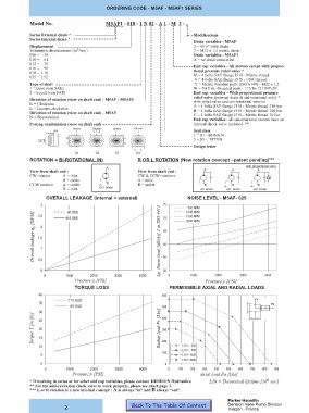
ORDERING CODE - M5AF - M5AF1 SERIES


             Model No.                    M5AF1 - 018 - 1 N 02 - A 1 - M 3 - ..

             Series External drain *                                        Modifications
             Series Internal drain *
                                                                            Drain variables - M5AF
             Displacement                                                   2 = 9/16” SAE drain
                               3
             Volumetric displacement (in /rev.)                             3 = M12 x 1,5 metric drain
             006 =   .38                                                    Drain variables - M5AF1
             010 =   .61                                                    X = no drain connection
             012 =   .76
             016 =   .98                                                    End cap variables - All motors except with propor-
                                                                            tional pressure relief valve *
             018 = 1.10
             025 = 1.52                                                     M = 4 bolts SAE flange J518 - Metric thread
                                                                            0 = 4 bolts SAE flange J518 - UNC thread
             Type of shaft                                                  Y = Metric threaded ports (ISO 6149) - M22 x 1,5
             1 = taper (non SAE)                                            W = SAE str. threaded ports - 1”1/16-12 UNF-2B
             2 = keyed (non SAE)                                            End cap variables - With proportional pressure
                                                                            relief valve (external drain & uni-rotational only) *
             Direction of rotation (view on shaft end) - M5AF - M5AF1       with relief valve and uni-rotational version
             R = Clockwise                                                  A = 4 bolts SAE flange J518 - Metric thread 210 bar
             L = Counter-clockwise                                          B = 4 bolts SAE flange J518 - Metric thread 140 bar
             Direction of rotation (view on shaft end) - M5AF               C = 4 bolts SAE flange J518 - Metric thread 70 bar
             N = Bi-rotational
                                                                            End cap variables : all uni-rotational motors have an
             Porting combination (view on shaft end)                        internal check valve included. **
                             DRAIN   DRAIN   DRAIN   DRAIN
                      A B            A  B                                   Seal class
                   DRAIN
                                                                            1 = S1 - BUNA N
                           B                     A                          5 = S5 -  VITON
                           A                     B
                                                                            Design letter
                                                     B  A
                              01      02     03      04
             ROTATION = BI-ROTATIONAL (N)             R OR L ROTATION (New rotation concept - patent pending)***
                                                                                                  with proportional valve
                                          A
             View from shaft end :                    View from shaft end :     A         A         A
             CW rotation  A = inlet                   CW & CCW rotations
                         B = outlet                   A = inlet
             CCW rotation  A = outlet     B           B = outlet                B         B         B
                         B = inlet     EXT. DRAIN                             INT. DRAIN  EXT. DRAIN  EXT. DRAIN
                   OVERALL LEAKAGE (internal + external)                 NOISE LEVEL - M5AF- 025
                 3                                              75         500 RPM
              [GPM]  2,5 2    60 SUS                            70       1000 RPM
                                                                         1500 RPM
                          115 SUS
                                                                         2000 RPM
              Overall leakage q s  1,5 1                       Lp. Noise level [db(A)] 1 m ISO 4412  60
                                                                65


                                                                55
                0,5
                 0                                              50
                  0       1000      2000     3000      4000       0       1000      2000     3000      4000
                              Pressure p [PSI]                                  Pressure p [PSI]
                              TORQUE LOSS                         PERMISSIBLE AXIAL AND RADIAL LOADS
                40                                             600
                           115 SUS                                                                 Fr
                35                                                                                       Fa
                             60 SUS
                30
              [in.lbs]  25                                     Radial load Fr [Lbs] 500           x  x
                                                               400
              Torque T  20                                     300
                15
                                                               200
                10                                                     L10 =   250
                                                                       L10 =   500
                                                               100
                 5                                                     L10 = 1000
                                                                       L10 = 2000
                 0                                               0
                  0       1000      2000     3000      4000       0   100  200  300  400  500  600  700  800  900
                             Pressure p [PSI]                                 Axial load Fa [Lbs]
                                                                                                        6
             * If working in series or for other end cap variables, please contact  DENISON Hydraulics.  L10 = Theoretical lifetime [10 rev.]
             ** For the anti-cavitation check valve to work properly, please see chart page 3.
             *** L or R rotation is a new internal concept : A is always “in” and B always “out”.
                                                                                         Parker Hannifin
                                                    Back To The Table Of Content         Denison Vane Pump Division
                          2                                                              Vierzon - France