Page 8 - Parker - Hydraulic flanges and components and dual seal flanges
P. 8

4300 Catalog                                                  Hydraulic Flanges and Components
                                                                                        and Dual Seal Flanges


            The Parker Advantage                                                                                     Return
                                                                                                                      To
                                                                                                                     Catalog
            Improved Pressure Rating: Parker’s new Dual Seal design is
            rated for up to 7500 PSI to meet current and future hydraulic
            design needs.  This design has also been tested to meet stan-
            dard SAE J1644 parameters.
            Captive O-ring Groove:  The design of Parker’s Dual Seal
            Flange Adapters incorporates a captive O-ring groove (CORG)
            which prevents O-ring fall out during installation further pre-
            venting the possibility of leaks.
            Radial Seal: The primary radial seal (A) improves the pres-
            sure capabilities of the Dual Seal system to 7500 PSI while
            offering additional system integrity.
            Ingression Seal: Reduces the potential for side loading and
            ultimately connection failure in high impulse and high vibration
            applications.

            Multiple Standard Configurations:  Parker’s Dual Seal
            Flange Adapter product line includes a variety of tube, pipe,
            and hose connection styles to meet hydraulic system design
            needs.  Included are Parker’s Seal-Lok (SAE J1453), Triple-
            Lok (SAE J514), SAE ORB (SAE J1926) and NPTF for tradi-
            tional hydraulic connections.  In addition, to offer a solution for
            schedule pipe assemblies, Parker offers socket weld configu-
            rations.


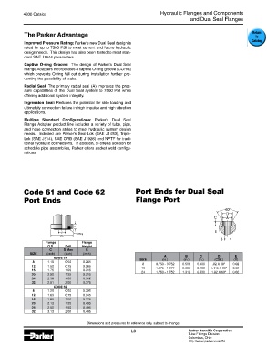
            Code 61 and Code 62                                Port Ends for Dual Seal

            Port Ends                                          Flange Port


                      Flange           Flange
                       O.D.    Drill   Height
                        C     D Max     E
               SIZE   (inch)   (inch)  (inch)
                                                                            A
                                                                                             C
                                                                                      B

                                                                                                     D
                                                                                                             E
                          CODE 61                                SIZE       (in.)    (in.)  (in.)  (CSK)    (R)
                8      1.19    0.50    0.265
                                                                  8
                                                                                                  .82 X 60°
                12     1.50    0.75    0.265                      16     0.750 - 0.752  0.500  0.400  1.445 X 60°  0.02
                                                                                     0.938
                                                                         1.375 - 1.377
                                                                                                            0.02
                                                                                           0.400
                16     1.75    1.00    0.315                      24     1.750 - 1.752  1.312  0.530  1.82 X 60°  0.02
                20     2.00    1.25    0.315
                24     2.38    1.50    0.315
                32     2.81    2.00    0.375
                          CODE 62
                8      1.25    0.50    0.305
                12     1.63    0.75    0.345
                16     1.88    1.00    0.375
                20     2.13    1.25    0.405
                24     2.50    1.50    0.495
                32     3.13    2.00    0.495
                                         Dimensions and pressures for reference only, subject to change.
                                                             L8                        Parker Hannifin Corporation
                                                                                       Tube Fittings Division
                                                                                       Columbus, Ohio
                                                                                       http://www.parker.com/tfd
   3   4   5   6   7   8   9   10   11   12   13