
Page 15 - Parker - Pressure Control Valves
P. 15
Catalog HY15-3502/US Direct Acting Relief Valve
Technical Information Series RDH101
CV
General Description
Direct Acting Relief Valve. This valve
is designed for pilot flow circuits. For
Check
Valves
SH additional information see Technical
Tips on pages PC1-PC6.
Shuttle
Valves
Features
LM
• Hardened, precision ground parts for durability
• Low profile adapter for minimal space requirements
• Fully guided poppet for more consistent reseat
Load/Motor
Controls
(2)
FC • Steel adapters are coated with yellow zinc dichromate for
protection from salt spray
• Polyurethane “D”-Ring eliminates backup rings and (1) (2) (1)
prevents hydrolysis
Controls
Flow
PC
Pressure
Controls
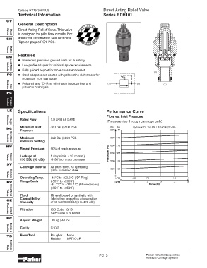
LE Specifications Performance Curve
Flow vs. Inlet Pressure
Rated Flow 1.9 LPM (.5 GPM)
(Pressure rise through cartridge only)
Elements
Logic
Maximum Inlet 380 Bar (5500 PSI) PSI Bar Hydraulic Oil 150 SSU @ 100°F (32 cSt)
DC
Pressure 6000 414
Maximum 350 Bar (5000 PSI) 5000 345
Pressure Setting
Directional
Controls
MV 4000 276
Reseat Pressure 90% of crack pressure
Leakage at 5 drops/min. (.33 cc/min.) Pressure, PSI 3000 207
150 SSU (32 cSt) @ 80% of crack pressure 2000 138
Valves
Manual
SV
Cartridge Material All parts steel. All operating
1000 69
parts hardened steel.
0
Operating Temp. -45°C to +93.3°C (“D”-Ring) LPM .38 .76 1.1 1.5 1.9
Valves
Solenoid
Range/Seals (-50°F to +200°F) 0
PV GPM .1 .2 .3 .4 .5
-31.7°C to +121.1°C (Fluorocarbon) Flow (Q)
(-25°F to +250°F)
Fluid Mineral-based or synthetic with
Valves
Proportional
Compatibility/ lubricating properties at viscosities
CE
Viscosity of 45 to 2000 SSU (6 to 420 cSt)
Filtration ISO Code 16/13,
SAE Class 4 or better
Coils &
Electronics
BC
Approx. Weight .18 kg (.40 lbs.)
Cavity C10-2
Bodies &
Cavities
TD Form Tool Rougher None
Finisher NFT10-2F
Data
Technical
PC13 Parker Hannifin Corporation
Hydraulic Cartridge Systems