
Page 3 - Parker - Metric clamps
P. 3
4300 Catalog Metric Clamps
Metric Clamps
The Parker Metric Clamp system is designed for restraining tube,
pipe and hose assemblies against unwanted, and potentially
harmful effects of mechanical shock and vibration forces that
are common in fluid power systems.
The clamping system is the most commonly overlooked aspect
of fluid power system design. Failure to properly restrain the fluid
conducting system can result in leakage, downtime and system
malfunction, as well as significantly reduced life of tube, pipe
and hose assemblies. With the Parker Metric Clamp system, the
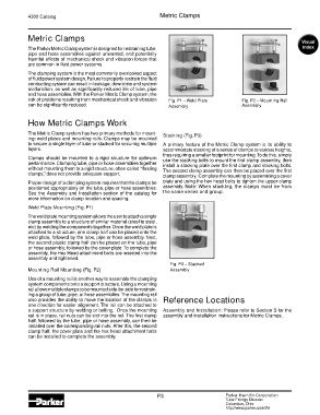
risk of problems resulting from mechanical shock and vibration Fig. P1 – Weld Plate Fig. P2 – Mounting Rail
can be significantly reduced. Assembly Assembly
How Metric Clamps Work
The Metric Clamp system has two primary methods for mount- Stacking (Fig. P3)
ing: weld plates and mounting rails. Clamps may be mounted
to secure a single layer of tube or stacked for securing multiple A primary feature of the Metric Clamp system is its ability to
layers. accommodate stacking of a series of clamps to various heights,
thus requiring a smaller footprint for mounting. To do this, simply
Clamps should be mounted to a rigid structure for optimum use the stacking bolts to mount the first clamp assembly, then
performance. Clamping tube, pipe or hose assemblies together install a stacking plate over the first clamp and stacking bolts.
without mounting them to a rigid structure, often called “floating The second clamp assembly can then be placed over the first
clamps,” does not provide adequate support. clamp assembly. Complete the mounting by assembling a cover
Proper design of a clamping system requires that the clamps be plate and using the hex head bolts to tighten the upper clamp
positioned appropriately on the tube, pipe or hose assemblies. assembly. Note: When stacking, the clamps must be from
See the Assembly and Installation section of the catalog for the same series and group.
more information on clamp location and spacing.
Weld Plate Mounting (Fig. P1)
The weld plate mounting system allows the user to attach a single
clamp assembly to a structure of similar material (steel to steel,
etc) by welding the components together. Once the weld plate is
attached to a structure, one clamp half can be placed onto the
weld plate, followed by the tube, pipe or hose assembly. Next,
the second plastic clamp half can be placed on the tube, pipe
or hose assembly, followed by the cover plate. To complete the
assembly, the Hex Head attachment bolts are inserted into the
assembly and tightened.
Fig. P3 – Stacked
Mounting Rail Mounting (Fig. P2) Assembly
Use of a mounting rail is another way to assemble the clamping
system components onto a support structure. Using a mounting
rail allows multiple clamps to be mounted side-by-side for restrain-
ing a group of tube, pipe, or hose assemblies. The mounting rail
also provides the ability to move the location of the clamps in Reference Locations
one direction for easier alignment. The rail can be attached to
a support structure by welding or bolting. Once the mounting Assembly and Installation: Please refer to Section S for the
rail is in place, rail nuts can be slid into the rail. The first clamp assembly and installation instructions for Metric Clamps.
half, followed by the tube, pipe or hose assembly, can then be
installed over the corresponding rail nuts. After this, the second
clamp half, the cover plate and the hex head attachment bolts
can be installed to complete the assembly.
P3 Parker Hannifin Corporation
Tube Fittings Division
Columbus, Ohio
http://www.parker.com/tfd