
Page 231 - Wago_Rail-MountedTerminalBlockSystems_Volume1_2015_US.pdf
P. 231
"
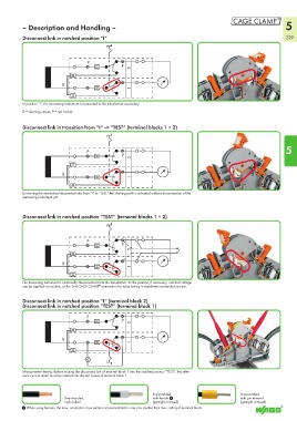
– Description and Handling – 5
Disconnect link in notched position “I“ 229
P
P
2
B
1
In position ”I“, the measuring instrument is connected to the transformer secondary.
B = shorting jumper, P = test socket
Disconnect link in transition from “I“ --> ”TEST“ (terminal blocks 1 + 2)
5
P
P
2
B
1
By moving the interlocked disconnect links from ”I“ to ”TEST“ the shorting path is activated without disconnection of the
measuring instrument yet.
Disconnect link in notched position ”TEST“ (terminal blocks 1 + 2)
P
P
2
B
1
The measuring instrument is electrically disconnected from the transformer. In this position, if necessary, external voltage
can be applied via sockets, or the 2nd CAGE CLAMP connection for relay testing in transformer protection circuits.
®
Disconnect link in notched position ”I“ (terminal block 2)
Disconnect link in notched position ”TEST“ (terminal block 1)
P
P
2
B
1
A
Measurement testing. Before moving the disconnect link of terminal block 1 into the notched position ”TEST“, the refer-
ence current meter must be inserted into the test socket of terminal block 1.
fine-stranded, fine-stranded,
fine-stranded, with ferrule 1 with pin terminal
tip-bonded (gastight crimped) (gastight crimped)
1 When using ferrules, the max. conductor cross section accommodated is one size smaller than max. rating of terminal block.