
Page 13 - Parker - AC10 Variable speed drive
P. 13
Variable Speed Drive - AC10
Connections
Connections
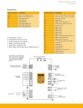
Power Terminals Description Control Terminals Description
L1/R Single or three phase input L1 TA Alarm N/O relay contact, 5A, 24V rated
L2/S Single or three phase input L2 TB Alarm N/C relay contact, 5A, 24V rated
L3/T Three phase input L3 TC Drive Alarm common
P Braking Resistor DO1 Digital Output 1
B Braking Resistor DO2 Digital Output 2 (Frames 6-11)
U Motor Output phase 1/U 24V 24 VDC Power output (max 50 mA)
V Motor Output phase 2/V CM 0 V DC common
W Motor Output phase 3/W DI1 Digital Input 1
DI2 Digital Input 2
DI3 Digital Input 3
DI4 Digital Input 4
DI5 Digital Input 5
DI6 Digital Input 6 (IP66 and Frames 6-11)
• Analog Input 1: (0-10 V) DI7 Digital Input (Frames 6-11)
• Analog Input 2: (0-10 V, 0-20 mA) DI8 Digital Input (Frames 6-11)
• Analog Outputs: (0-10 V, 0-20 mA) 10V 10 V Reference supply (max 20 mA)
AI1 Analog input 1
• Digital Inputs: Nominal 24 VDC
• Digital Output: Nominal 24 VDC AI2 Analog input 2
GND Power Supply 0V
• Relay Output: Volt free (dry) contact, 5A@230 VAC max
AO1 Analog Output 1
AO2 Analog Output 2 (Frame 6-11)
A+ RS485 Channel A
B- RS485 Channel B
This illustration is for reference only,
and may not show the connections Braking Resistor (Optional)
for your specific drive. Please refer
to the specific product installation
manual for detailed connection
diagram.
Single/Three Phase Input
230/480 VAC 50/60 Hz
Relay Output
5A/230VAC or 30VDC
Digital Input
Terminals
Analog Output 1
0-10 V
Multifunction Output
(24 VDC)
2.2 kΩ/1 W
Analog Inputs
0-20 mA
Modbus
Communications
13