
Page 27 - Parker - Rodless Air Cylinders
P. 27
Catalog #AU03-0928/NA Rodless Air Cylinders
Moments / Load and Deflection P1X Series
Moments Figure 6
Figure 5 shows the maximum allowable moments for each Max. Allowable Max. Unsupported
of the three types of loading: Bending, Radial, and Cross Bore Load [L] N (Lbs.) Length mm (in)
moments.
Std. Inverted at Max. Load
The sum total of each of these types of moments, divided by 16 141 (32) 70 (16) 450 (17.7)
each of the maximum values, determines a Load-Moment 20 198 (45) 101 (23) 551 (21.7)
Factor (LMF) should be equal to or less than 1.0. On 25 356 (81) 180 (41) 899 (35.4)
horizontal mountings, the total load (L) should also be 32 616 (140) 308 (70) 749 (29.5)
divided by the maximum load allowable (Figure 6) and 40 959 (218) 480 (109) 1000 (39.4)
factored into the equation.
50 1456 (331) 726 (165) 1300 (51.2)
Horizontal Mountings: 63 2297 (522) 1148 (261) 1600 (63.0)
B
Acceptable length and load combinations for the various
bore sizes can be determined from the charts in Figure 11.
Vertical Mountings:
Figure 7
Figure 5
Maximum Allowable Moments N-m (In-Lbs)
[M] [Ms] [Mv]
Bore Bending Radial Cross
Moment Moment Moment
Std. Inverted Std. Inverted Std. Inverted
16 5 (44) 3.5 (31) 1 (9) 0.5 (4) 1 (9) 1 (9)
20 10 (89) 7 (62) 1.5 (13) 0.7 (6) 3 (27) 3 (27)
25 17 (150) 12 (106) 5 (44) 2.5 (22) 10 (89) 10 (89)
32 36 (319) 25 (221) 10 (89) 5 (44) 21 (186) 21 (186)
40 77 (682) 54 (478) 23 (204) 11.5 (102) 26 (230) 26 (230)
50 154 (1363) 108 (956) 32 (283) 16 (142) 42 (372) 42 (372)
63 275 (2434) 193 (1708) 52 (460) 26 (230) 76 (673) 76 (673)
Load and Deflection
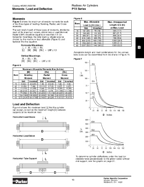
Figure 6 shows the maximum load [L] that the cylinder
can accept, as well as the maximum length [D] between
supports at the maximum load.
Horizontal–Load Above
L
D
Horizontal–Load Below
D
L
To determine cylinder deflections under the load (or
Horizontal–Tube Support L resistive force perpendicular to the piston table) without
mid-support, see the graphs on page 21.
D D
Parker Hannifin Corporation
19 Actuator Division
Wadsworth, OH 44281