
Page 3 - Proportion-Air - FCV Electro-Pneumatic Flow Valve
P. 3
GENERAL SPECIFICATIONS
ELECTRICAL
POWER REQUIREMENT 15-24 VDC @ 250mADC
COMMAND SIGNAL Differential 4-20mA or differential 0-10VDC (Field Selectable)
VALVE POSITION MONITOR 4-20mA sourcing or 0-10VDC (Field Selectable)
MECHANICAL
MEDIA WORKING PRESSURE Maximum: 250 PSIG (17.25 BAR)
ACTUATOR LOADING PRESSURE Minimum: 80 PSIG (5.5 BAR),
Maximum: 120 PSIG (8.25 BAR)
VALVE Cv 0 to 19 Linear to Command
Kv 0 to 16.4 Linear to Command
END CONNECTIONS 1” NPT Threaded
RESOLUTION 0.3% Typical
LINEARITY +/- 5%
WETTED MATERIALS 316 SS and Reinforced PTFE Seals
PHYSICAL
MEDIA WORKING TEMPERATURE Maximum: 356ºF [180ºC]
AMBIENT TEMPERATURE 32-158ºF [0-70ºC]
WEIGHT 10 lbs [4.5 Kg]
ACTUATOR HOUSING RATING IP65
OPERATING MODES'
FCVxxxxxNVC FCVxxxxxNC FCVxxxxxNVO FCVxxxxxNO
(normally closed, venting) (normally closed, non-venting) (normally open, venting) (normally open, non-venting)
POWER LOSS Closes Hold Opens Hold
AIR LOSS Closes Closes Opens Opens
0VDC or 4mA Closed Fully Open
10VDC or 20mA Fully Open Closed
'Operating modes indicate the function of the valve during normal use and operation only. Operating modes indicated should not be relied upon for safety.
Venting: upon loss of power, loading pressure on actuator is relieved to atmosphere allowing the valve spring to return to its normal operating mode.
Non-Venting: upon loss of power, pressure is trapped causing the actuator to hold loading position until loading pressure is decayed.
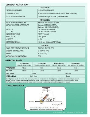
TYPICAL APPLICATION
Control
Out In
T
Mold
C
SUPPLY
FCV
To Cooling Tower
FCV controls cooling water flow to a die casting mold.
Thermocouple (TC) provides temperature feedback to control.
LET’S TALK 317-335-2602 * PROPORTION-AIR * BRFCV1207E 3