
Page 6 - Parker - Logic Elements
P. 6
Catalog HY15-3502/US
Technical Tips Logic Elements
CV
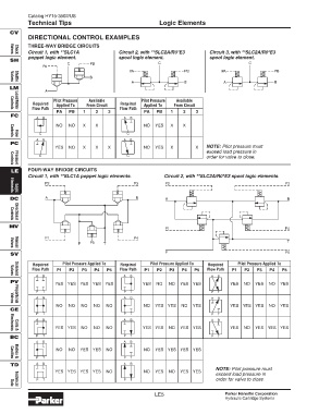
DIRECTIONAL CONTROL EXAMPLES
THREE-WAY BRIDGE CIRCUITS
Circuit 1, with **SLC1A Circuit 2, with **SLC2A/R0*E3 Circuit 3, with **SLC2A/R0*E3
Check
Valves
poppet logic element. spool logic element. spool logic element.
SH
C PB C C
PA
PA PB PA PB
B
A B A B
Valves
Shuttle
LM
A
Pilot Pressure Available Pilot Pressure Available
Required Applied To From Circuit Required Applied To From Circuit
Flow Path Flow Path
Load/Motor
Controls
PA PB 1 2 3 PA PB 1 2 3
FC
A B A B
NO NO X X NO YES X X
C C
Flow
Controls
A B A B
PC
YES NO X X X NO YES X X NOTE: Pilot pressure must
exceed load pressure in
C C order for valve to close.
Controls
Pressure
LE FOUR-WAY BRIDGE CIRCUITS
Circuit 1, with **SLC1A poppet logic elements. Circuit 2, with **SLC2A/R0*E3 spool logic elements.
P2 P3 P2 P3
Logic
Elements
DC A B A B
Directional
Controls
MV
P1 P4
P1 P4
P P5 T T
Manual
Valves
SV P P5
Required Pilot Pressure Applied To Required Pilot Pressure Applied To Required Pilot Pressure Applied To
Flow Path P1 P2 P3 P4 P5 Flow Path P1 P2 P3 P4 P5 Flow Path P1 P2 P3 P4 P5
A B A B A B
Solenoid
Valves
PV
YES YES YES YES YES YES NO NO YES YES YES NO YES NO YES
P T P T P T
A B A B A B
Valves
Proportional
NO NO NO NO NO NO YES YES NO YES YES YES YES NO YES
CE
P T P T P T
A B A B A B
YES YES NO NO NO YES YES NO YES YES YES NO YES YES YES
Coils &
Electronics
BC P T P T P T
A B A B
NO NO YES YES NO NO YES YES YES YES
P T P T
Cavities
Bodies &
TD A B A B
NOTE: Pilot pressure must
YES YES YES YES NO NO YES NO YES YES
exceed load pressure in
P T P T order for valve to close.
Data
Technical
LE5 Parker Hannifin Corporation
Hydraulic Cartridge Systems