
Page 4 - Parker - K4 BSP Adapters
P. 4
4300 Catalog K4 BSP Adapters
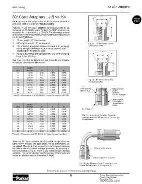
60° Cone Adapters: JIS vs. K4
K4 Adapters, while very similar to JIS P4 cones (shown in
previous section), are not interchangeable.
Parker’s P4 JIS 60° cone adapters are manufactured in ac-
cordance to JIS B8363 while Parker’s K4 BSP adapters are
manufactured in accordance to BS5200. The following are some
pronounced differences that may help in distinguishing between
the K4 and P4 fittings:
1. Thread length (“A” dimensions)
2. 60° angle diameter (“B” dimensions) Fig. I3 – JIS B8363 60° Cone
3. The undercut area (area between threads and hex body) Connection (P4)
on the straight K4 fittings incorporates a bonded seal
“locating pilot” for bonded seal
4. Parker’s JIS fittings are stamped with “JIS” on the forging
body or hex of fitting
See Figs. I3 and I4 for details and see Tables I2 and I3 below
for specific dimensional differences.
BSPP
Size Thread M A B
2 1/8-28 0.38 0.418 0.276
4 1/4-19 0.51 0.570 0.394
6 3/8-19 0.65 0.609 0.531
8 1/2-14 0.82 0.726 0.650 Fig. I4 – BS B5200 60° Cone
12 3/4-14 1.04 0.805 0.866 Connection (K4)
16 1-11 1.30 0.883 1.102
20 1 1/4-11 1.64 0.945 1.417
24 1 1/2-11 1.87 0.962 1.654
32 2-11 2.34 1.102 2.126
Table I2 – Dimensions of JIS B8363 60° Cone Connection (JIS P4)
BSPP
Size Thread M A B
2 1/8-28 0.38 0.315 0.295
4 1/4-19 0.51 0.433 0.409
6 3/8-19 0.65 0.472 0.551 Fig. I5 – Illustration Showing Potential
8 1/2-14 0.82 0.551 0.689 Leakage Problem When Mixing JIS and K4
10 5/8-14 0.90 0.630 0.760 Components
12 3/4-14 1.04 0.630 0.902
16 1-11 1.30 0.748 1.130
20 1 1/4-11 1.64 0.787 1.449
24 1 1/2-11 1.87 0.866 1.681
32 2-11 2.34 0.984 2.150
Table I3 – Dimensions of BS B5200 60° Cone Connection (K4)
While the 60° cone versions of JIS and K4 fittings utilize the
same BSPP threads and seat angle, not all dimensions are
consistent. Therefore, they cannot be interchanged because
the differences can cause leakage problems. An example of
this is illustrated in Fig. I5, where a gap exists between sealing
surfaces. The combination of matching proper components will
create an effective seal as illustrated in Fig I6.
Fig. I6 – An Effective Seal Created with the
Proper Combination of Components
Dimensions and pressures for reference only, subject to change.
I4 Parker Hannifin Corporation
Tube Fittings Division
Columbus, Ohio
http://www.parker.com/tfd