Page 261 - Destaco - Clamping Technology
P. 261

Funktionsschema
                                                                                                   Grundstellung
                                                                                                   Anstellhub
                                                                                                   Gleiche Kraft wie ein konventioneller Pneumatikzy-
                                                                                                   linder mit entsprechendem Kolbendurchmesser.
                                                                                                   Krafthub
                                                                                                   Die mechanische Kraftübersetzung tritt in Funk-
                                                                                                   tion. Mechanische Kraftübersetzung max. 10 :1.
                                                                                                   Rückhub
                                                                                                   Der Rückhub kann in jeder beliebigen Kolbenstel-
                                                                                                   lung eingeleitet werden. Die Rückstellkraft beträgt  Pneumatik-Kraftzylinder
                                                                                                   ca. die Hälfte der Anstellkraft.
                                                                                                     -A option
                                                                                                            Magnetfeldabfragung
                                                                Magnetic Field Sensing | Technical Specifications
                                    NEU!
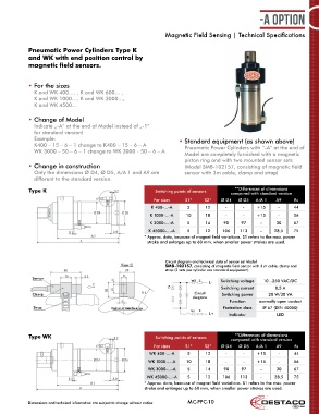
            Pneumatic Power Cylinders Type K
            and WK with end position control by
                                    Pneumatik-Kraftzylinder der Bauform K und WK
            magnetic field sensors.
                                    mit Magnetfeldabfragung
            • For the sizes            für die Größen
              K and WK 400…. , K and WK 600… ,                                                                     Technische Daten und
                                      K bzw. WK 400-..., K bzw. WK 1000-...
              K and WK 1000…. K and WK 3000…,                                                                      Maßunterschiede zur
              K and WK 4500…          K bzw. WK 3000-..., K bzw. WK 4500-...                                       Standardausführung
                                                                                                                   siehe Seite 20.4 und
                                                                                                                   20.6!
            • Change of Model          Modell-Nr.-Änderung
              Indicate „-A“ at the end of Model instead of „-1“
                                      „-A“ am Ende der Modell-Nr. für Standard-Ausführung anstelle
              for standard version!   von „-1“ einsetzen!
              Example:                                                • Standard equipment (as shown above)
                                                                                         Lieferumfang
                                      Beispiel: K 400-15-6-1 wird zu K 400-15-6-A
              K400 – 15 – 6 – 1 change to K400 – 15 – 6 – A             Pneumatic Power Cylinders with “-A” at the end of
              WK 3000 – 50 – 6 – 1 change to WK 3000 - 50 – 6 – A       Model are completely furnished with a magnetic
                                                                                        Die Zylinder mit -A am Ende der Modell-Nr. sind serienmäßig mit
                                                  WK 3000-50-6-1 wird zu WK 3000-50-6-A
                                                                                        einem Magnetkolben ausgestattet.
                                                                        piston ring and with two mounted sensor sets
            • Change in construction                                    (Model SMB-102157, consisting of magnetic field
                                       Bauliche Änderungen
                                                                                        Separat zu bestellen:
              Only the dimensions Ø D4, Ø D5, A/A 1 and A9 are          sensor with 3m cable, clamp and strap)
                                                                                        Pro Zylinder je 2 Stück Magnetfeldschalter-Sets, Modell-Nr.
                                      Lediglich die Maße Ø D4, Ø D5, A/A 1  und A9 unterscheiden sich
              different to the standard version.
                                      zur Standardausführung.                           SMB-102157, bestehend aus Sensor mit 3 m Kabel, Klemmbock
                                                                                           **Differences of dimensions
            Type K                    Siehe Seite 20.4 und 20.6!  Switching points of sensors  und Spannband.
                                                                                          compared with standard version
                                                                                        Siehe Seite 20.4 und 20.6!
                                                            For sizes   S1*     S2*   Ø D4   Ø D5  A/A 1   A9     Rs
                                                           K 400-...-A   5      12      -     -     +15     -     44
                                                           K 1000-...-A  10     18      -     -     +15     -     56
                                                           K 3000-...-A  5      14     90     97     -     30     67
                                   DE-STA-COA-CO
                                   DE-ST                  K 45000-...-A  5      12    106    113     -    28,5    75                  20.2
                                                        *  Approx. data, because of magnet field variations. S1 refers to the max. power
                                                          stroke and enlarges up to 60 mm, when smaller power strokes are used.
                                                                Circuit diagram and technical data of sensor set Model
                                               View C           SMB-102157, consisting of magnetic field sensor with 3 m cable, clamp and
                                                                strap (2 sets per cylinder are standard equipment).
             Sensor
                                                                          ws E        Switching voltage  10...250 VAC/DC
                                                                                 L-
                                                                                      Switching current    0,5 A
             Clamp                                                          Circuit    Switching power  20 W/30 VA
                                                                           diagram
                                                                                         Function   normally open contact
              Strap                         Radius of interference                     Protection class  IP 67 (DIN 40050)
                                                                          bn  E
                                                                                 L+      Indicator         LED


            Type WK                                          Switching points of sensors   **Differences of dimensions
                                                                                          compared with standard version
                                                            For sizes   S1*     S2*   Ø D4   Ø D5  A/A 1   A9     Rs
                                                          WK 400-...-A   5      12      -     -     +15     -     44
                                                          WK 1000-...-A  10     18      -     -     +15     -     56
                                                          WK 3000-...-A  5      14     90     97     -     30     67
                                                         WK 45000-...-A  5      12    106    113     -    28,5    75
                                                        * Approx. data, because of magnet field variations. S1 refers to the max. power
                                                        stroke and enlarges up to 60 mm, when smaller power strokes are used.


            Dimensions and technical information are subject to change without notice  MC-PPC-10
   256   257   258   259   260   261   262   263   264   265   266